
Fuel Level Monitor with 15 Segments Bar-Graph Display
- Rajkumar Sharma
- 103 Views
- easy
- Tested
- SKU: EL150128
- Quote Now
- 0 Likes

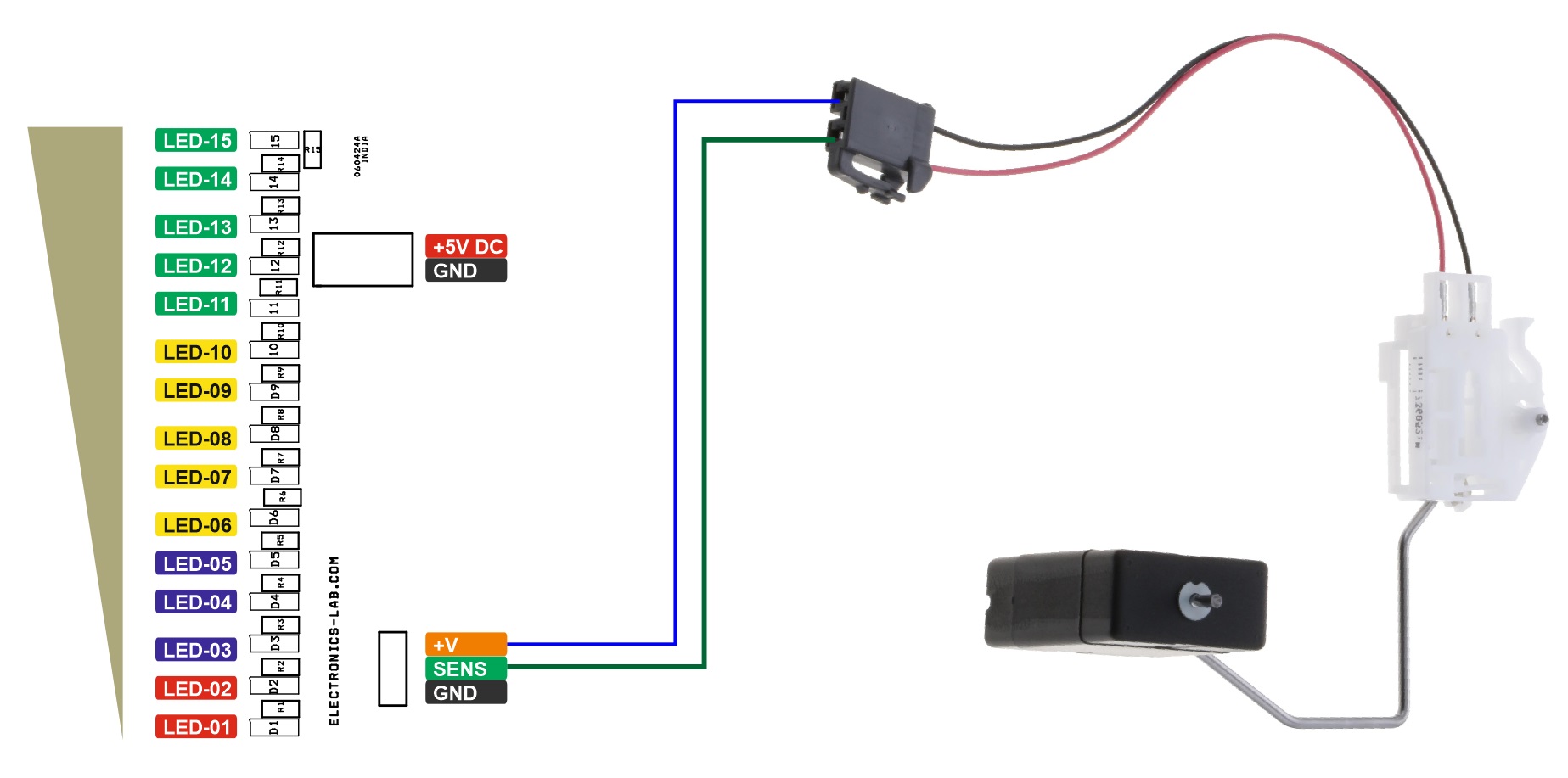
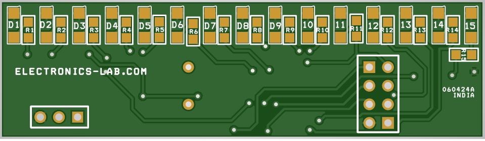
This Fuel level Monitor allows users to measure the fuel level using a resistive float sensor in the fuel tank. The project measures the fuel level and displays it on a 15-segment bar-graph display. The project is Arduino-compatible and consists of ATMEGA328 controller. The resistive sensor with a divider resistor is connected to Analog pin A0 of the MCU chip. The 15 LEDs of different colors are connected to various Arduino pins.
Arduino Code
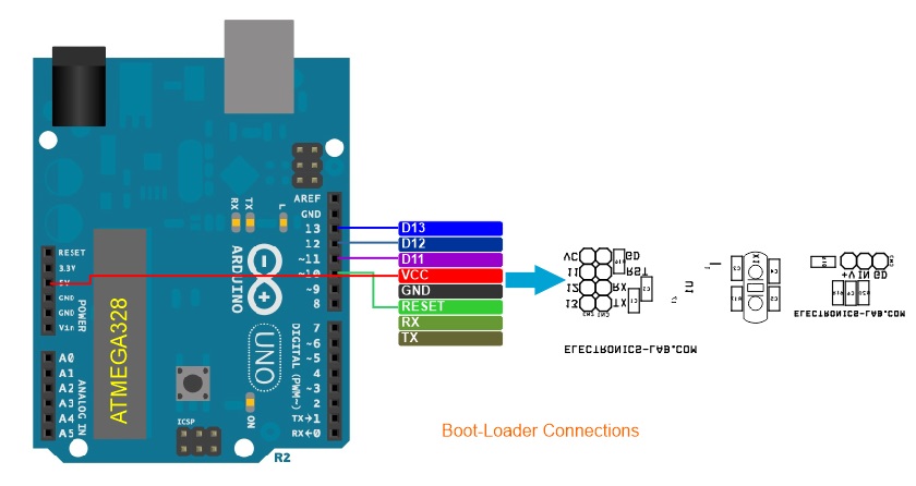
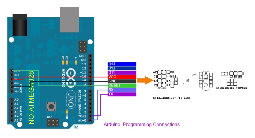
Arduino code is available to test the project. Burn the bootloader and code to a new ATMEGA328 microcontroller using the onboard programming connector. Refer to the connection diagrams below.
Bootloader: https://docs.arduino.cc/retired/hacking/software/Bootloader/
Arduino Bootloader and Arduino Programming:https://docs.arduino.cc/built-in-examples/arduino-isp/ArduinoToBreadboard/
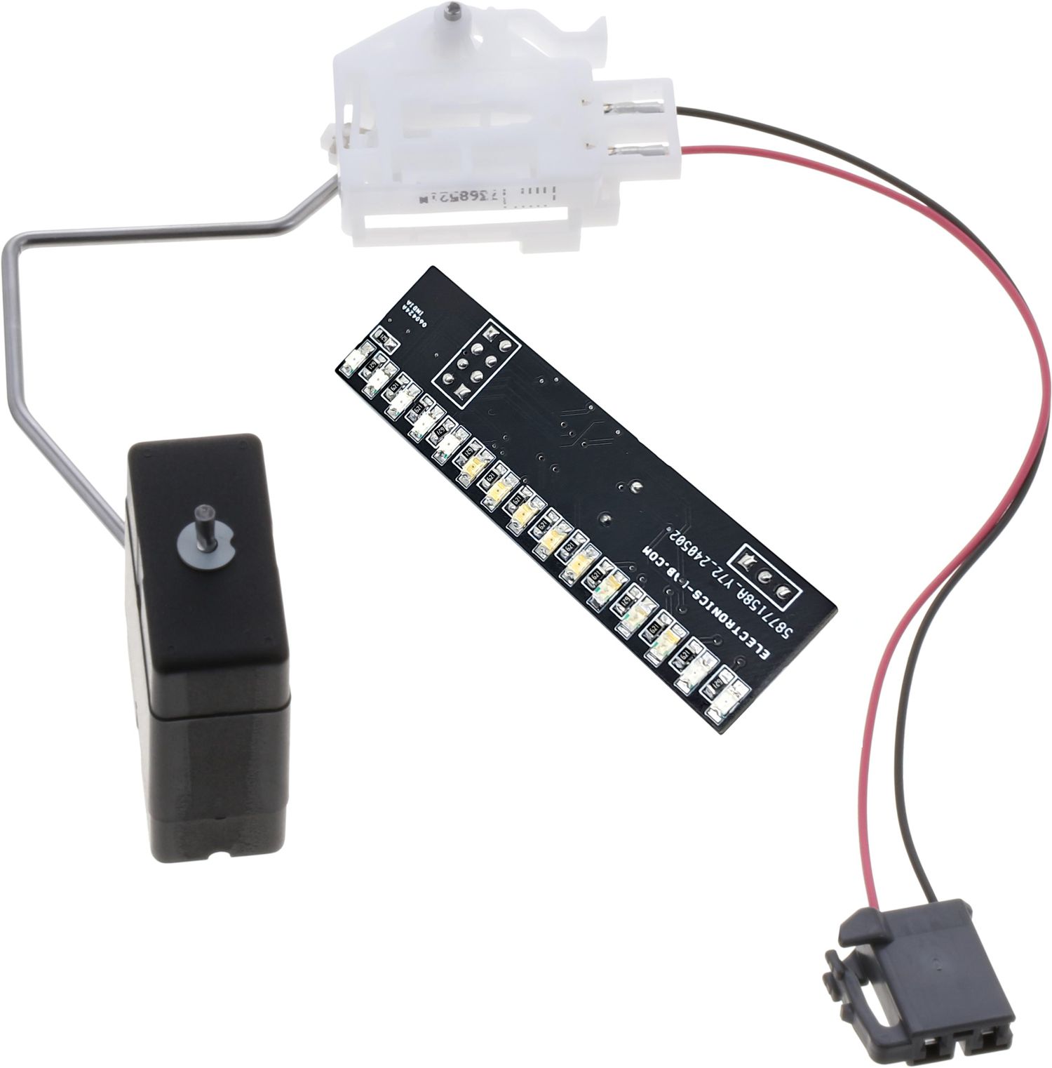
Sensor
A resistive sensor is used to measure the fuel level. This sensor with 1kΩ divider resistor outputs analog values 785 to 984. This analog signal is connected to ADC A0 of the Arduino chip. Arduino chip evaluates input signal and controls 15LEDs. Different sensor provides different outputs. It is advisable to map the right value in Arduino code as per the sensor’s output.
Features
- Power Supply 5V DC
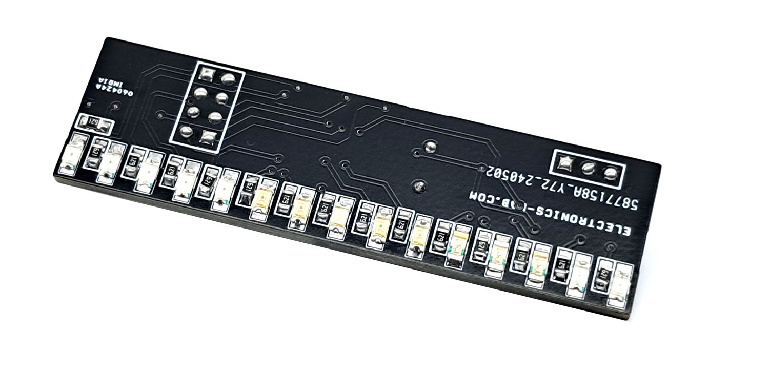
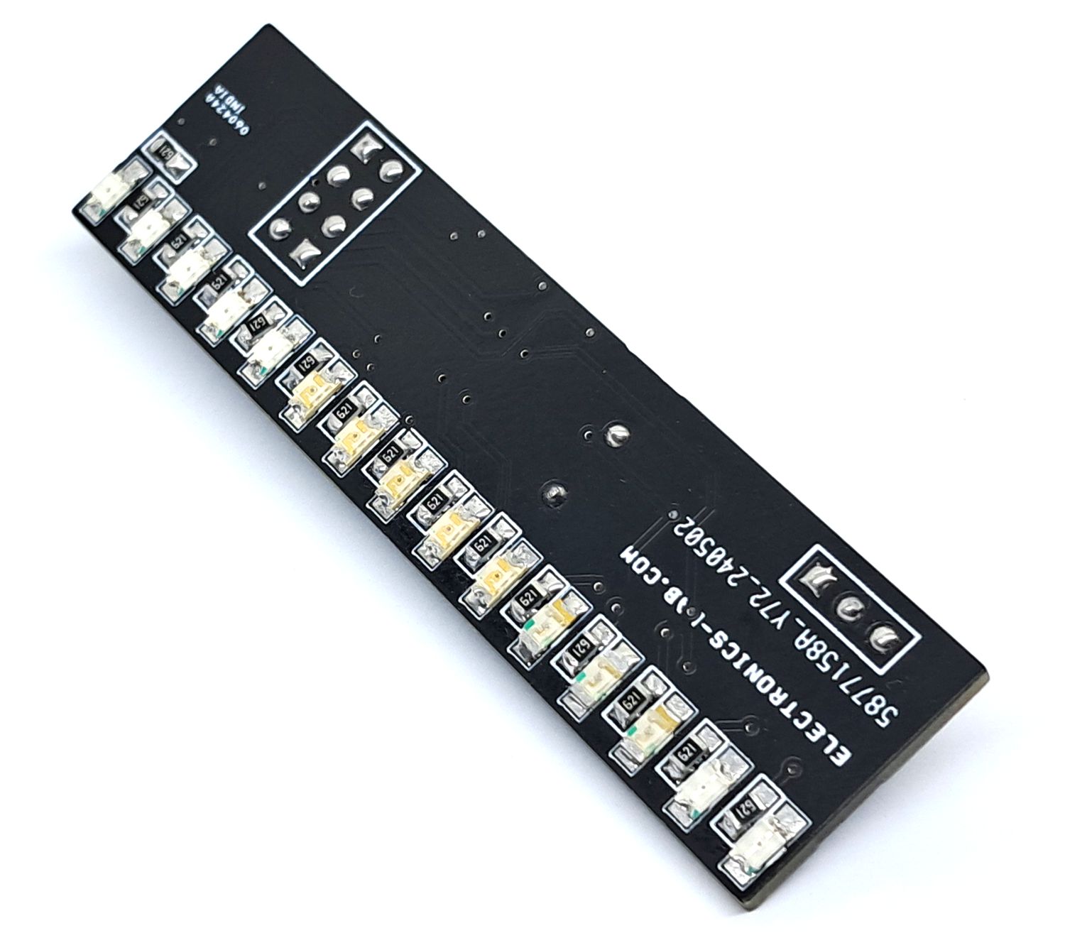
- 15 Segments Bar-Graph Display
- Arduino Compatible Project
- Project Accommodates Any Resistive Sensor 2 Wire or 3 Wire
- Multicolor LEDs Used for Easy Visualisation
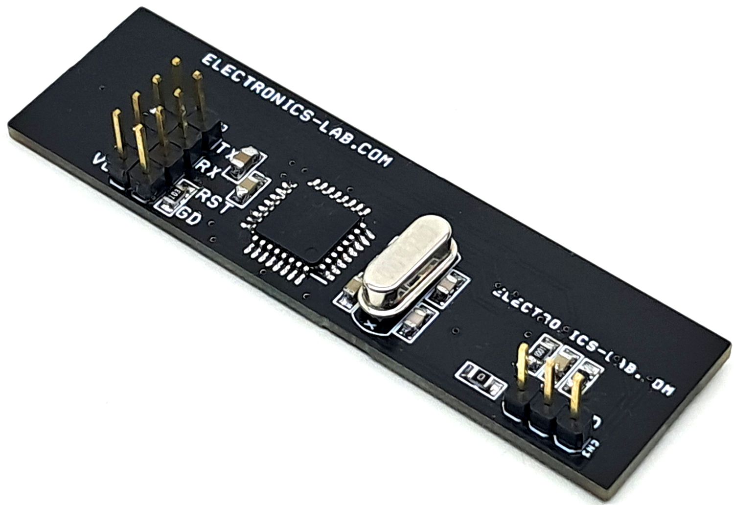
- On Board Connector for Bootloader and Arduino Programming
- PCB Dimensions 65.41 x 18.42mm
Arduino Pins
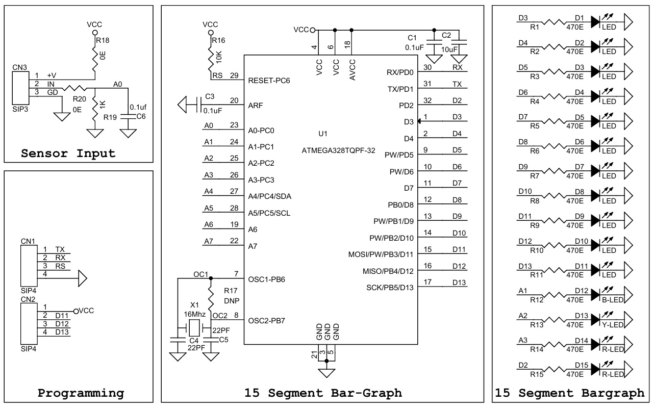
- Sensor Input Analog-0 Arduino
- Arduino D3 = LED01
- Arduino D4 = LED02
- Arduino D5 = LED03
- Arduino D6 = LED04
- Arduino D7 = LED05
- Arduino D8 = LED06
- Arduino D9 = LED07
- Arduino D10 = LED08
- Arduino D11 = LED09
- Arduino D12 = LED10
- Arduino D13 = LED11
- Arduino A1 = LED12
- Arduino A2 = LED13
- Arduino A3 = LED14
- Arduino D2 = LED15
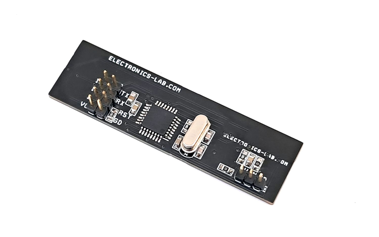
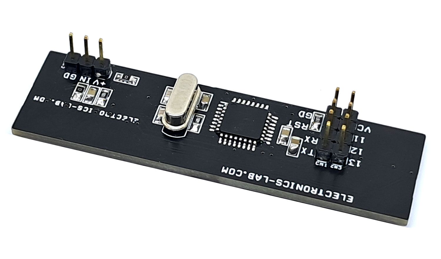
Connections
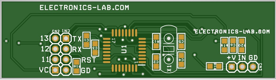
- CN1: Programming Pin 1 = TX, Pin 2 = TX, Pin 3 = Reset, Pin 4 = GND
- CN2: Programming Pin 1 = VCC, Pin 2 = D11, Pin 3 = D12, Pin 4 = D13
- CN3: Pin 1 = Sensor 1, Pin 2 = Sensor 2, Pin 3 = GND No Use
Schematic
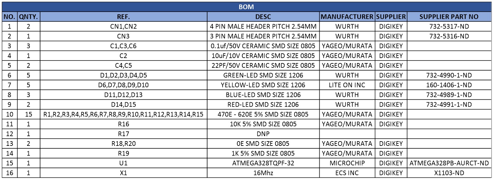
Parts List
| NO. | QNTY. | REF. | DESC | MANUFACTURER | SUPPLIER | SUPPLIER PART NO |
|---|---|---|---|---|---|---|
| 1 | 2 | CN1,CN2 | 4 PIN MALE HEADER PITCH 2.54MM | WURTH | DIGIKEY | 732-5317-ND |
| 2 | 1 | CN3 | 3 PIN MALE HEADER PITCH 2.54MM | WURTH | DIGIKEY | 732-5316-ND |
| 3 | 3 | C1,C3,C6 | 0.1uf/50V CERAMIC SMD SIZE 0805 | YAGEO/MURATA | DIGIKEY | |
| 4 | 1 | C2 | 10uF/10V CERAMIC SMD SIZE 0805 | YAGEO/MURATA | DIGIKEY | |
| 5 | 2 | C4,C5 | 22PF/50V CERAMIC SMD SIZE 0805 | YAGEO/MURATA | DIGIKEY | |
| 6 | 5 | D1,D2,D3,D4,D5 | GREEN-LED SMD SIZE 1206 | WURTH | DIGIKEY | 732-4990-1-ND |
| 7 | 5 | D6,D7,D8,D9,D10 | YELLOW-LED SMD SIZE 1206 | LITE ON INC | DIGIKEY | 160-1406-1-ND |
| 8 | 3 | D11,D12,D13 | BLUE-LED SMD SIZE 1206 | WURTH | DIGIKEY | 732-4989-1-ND |
| 9 | 2 | D14,D15 | RED-LED SMD SIZE 1206 | WURTH | DIGIKEY | 732-4991-1-ND |
| 10 | 15 | R1 to R15 | 470E - 620E 5% SMD SIZE 0805 | YAGEO/MURATA | DIGIKEY | |
| 11 | 1 | R16 | 10K 5% SMD SIZE 0805 | YAGEO/MURATA | DIGIKEY | |
| 12 | 1 | R17 | DNP | |||
| 13 | 2 | R18,R20 | 0E SMD SIZE 0805 | YAGEO/MURATA | DIGIKEY | |
| 14 | 1 | R19 | 1K 5% SMD SIZE 0805 | YAGEO/MURATA | DIGIKEY | |
| 15 | 1 | U1 | ATMEGA328TQPF-32 | MICROCHIP | DIGIKEY | ATMEGA328PB-AURCT-ND |
| 16 | 1 | X1 | 16Mhz | ECS INC | DIGIKEY | X1103-ND |
Connections
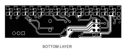
Gerber View
Photos
Video
ATMEGA328 Datasheet
Please follow and like us:
PCB


Subscribe
Login
0 Comments


