Getting Started with ESP32
- Emmanuel Odunlade
- https://twitter.com/emmaodunlade
- emmaodunlade@gmail.com
- 14.311 Views
- moderate
- Tested
Over the last few articles, we have covered the use of ESP8266 boards for building several WiFi based projects. For today’s tutorial, we will look at it’s recently released successor; the ESP32.
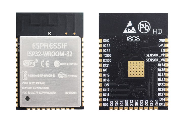
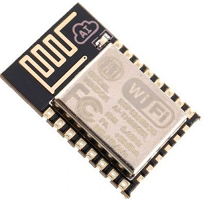
As mentioned in previous tutorials, ESP-12e module popularly referred as the nodeMCU came at a time where makers were struggling with the difficulties around the use of the ESP-01 modules. The ESP-01 modules were not breadboard compatible, had power issues, and could barely be used in a standalone application where more than two GPIOs are required. The NodeMCU solved all these issues adding additional features and it immediately became a darling of the maker community. However, the ESP8266 equally had its own limitations and like every good product, there was a need to improve it. This improvement came in the form of the ESP32.
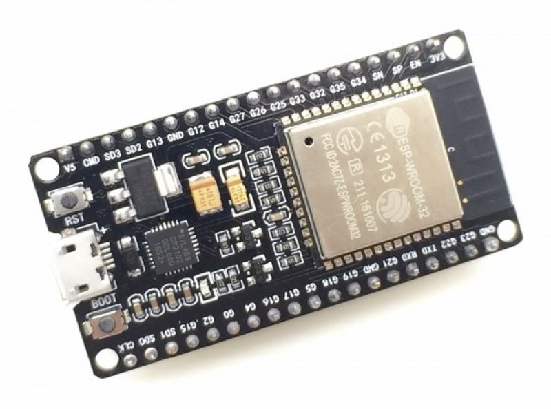
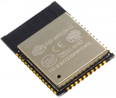
The ESP32 is way advanced compared to the ESP-12e. Among several features, the ESP32 packs a CPU core, a faster Wi-Fi, more GPIOs (especially increased analog pins that we all desired), supports Bluetooth 4.2 and Bluetooth low energy. The board also comes with touch-sensitive pins, alongside a built-in hall effect and temperature sensors. While both boards are quite cheap, the ESP32 ($6 – $12) costs slightly more than the ESP-12e ($3-$6).
The table below provides a more detailed comparison between the two modules.
Today’s tutorial will not only provide a comparison between these boards, but it will also show you how to put the ESP32 board to use. We will look at setting up the ESP32 module for programming with the Arduino IDE and we will run the Arduino blink example on the board. This will allow you to setup all that is needed for the exciting projects we will build with this new board over the next few tutorials.
Required Components
The following components are required for this tutorial;
- ESP32 based development board ( I will be using the DOIT DEVKIT V1 board)
- Breadboard
- Jumper wires.
- 100 Ohms resistor
- LED
The tutorial should work with any ESP32 based board. The choice of the DOIT DevKIT V1 is as a result of its availability and general popularity.
Schematics
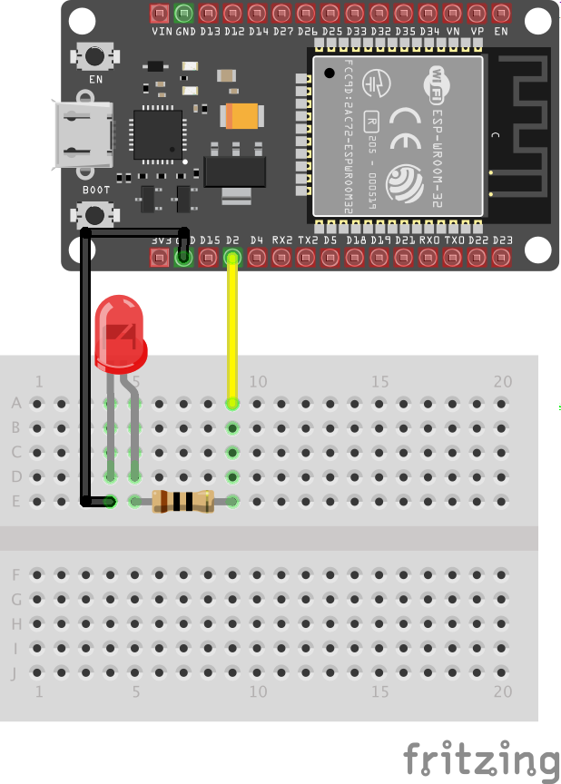
We will connect a LED to the ESP32 such as that the LED blinks as the popular blink example.
Connect the LED to the ESP32 as shown below.
Programming the ESP32
Like the ESP-12e modules and boards, the ESP32 modules and boards can also be programmed with LUA on the ESPlorer IDE or with C/C++ on the Arduino IDE. However, like the ESP8266, we will need to install the ESP32 core and board files on the Arduino IDE before it can be used to upload code to the ESP32.
The process of installing the ESP32 core on the Arduino IDE is similar to the one we followed to install the ESP8266 Arduino Core. Follow the steps below:
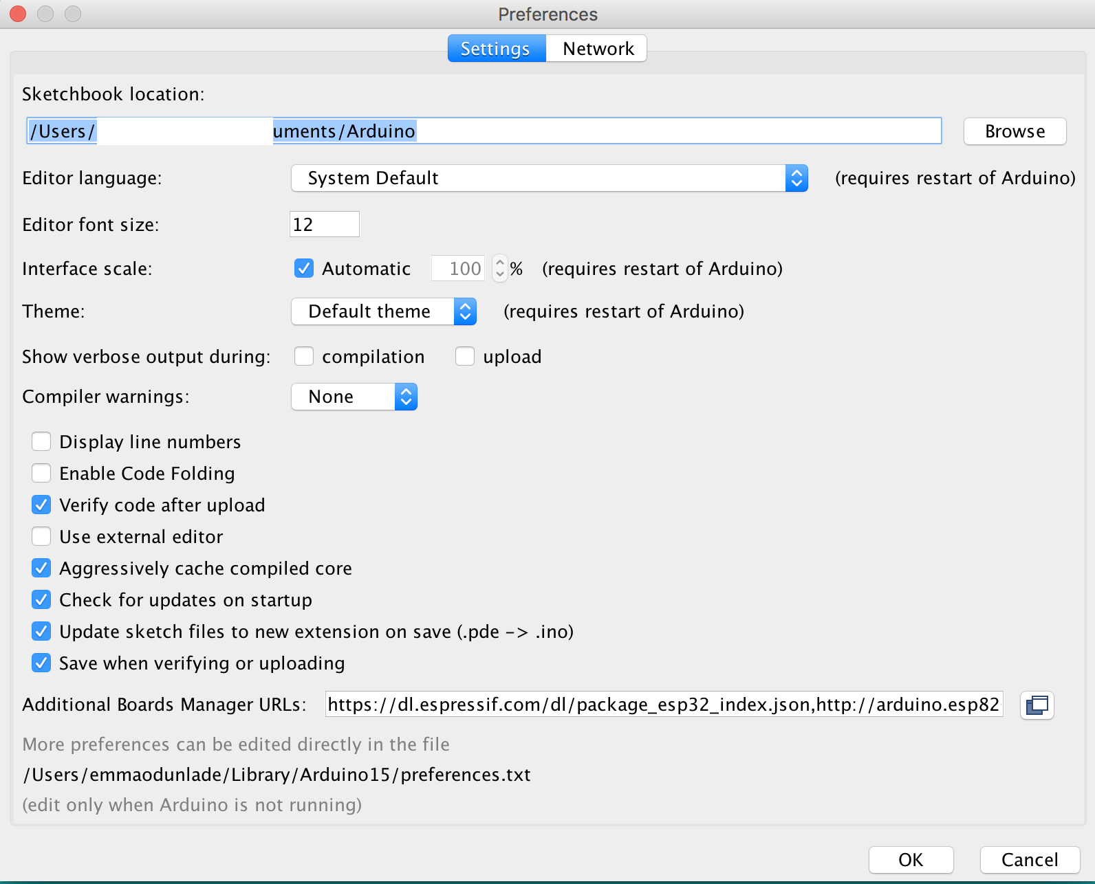
– Open the preferences window from the Arduino IDE. Go to File > Preferences
– On the preferences window, locate the “Additional Board Manager URLs” text box and enter https://dl.espressif.com/dl/package_esp32_index.json into the field as shown below. As you may have other URLs there already, separate the URLs from each other using a comma (“,”) and click OK when done.
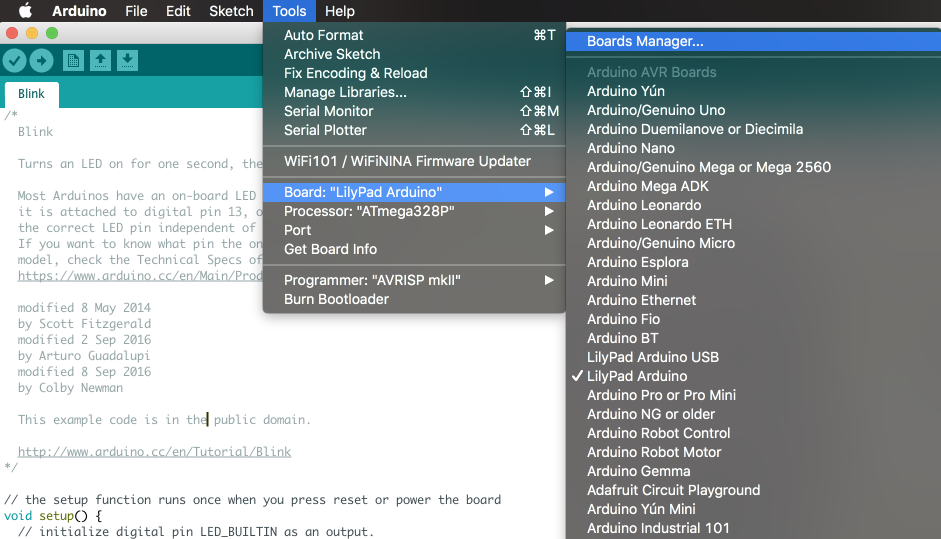
– Next, open the Arduino board manager. Go to tools > Boards > Boards manager
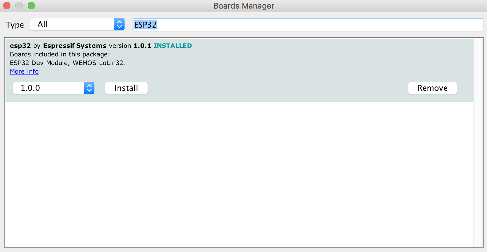
– When the board manager opens up, enter ESP32 into the search bar and scroll to the bottom, you will see “ESP32 by Espressif systems”, click on install.
With that done, you should now see quite a number of ESP32 based boards under the Arduino Board list.
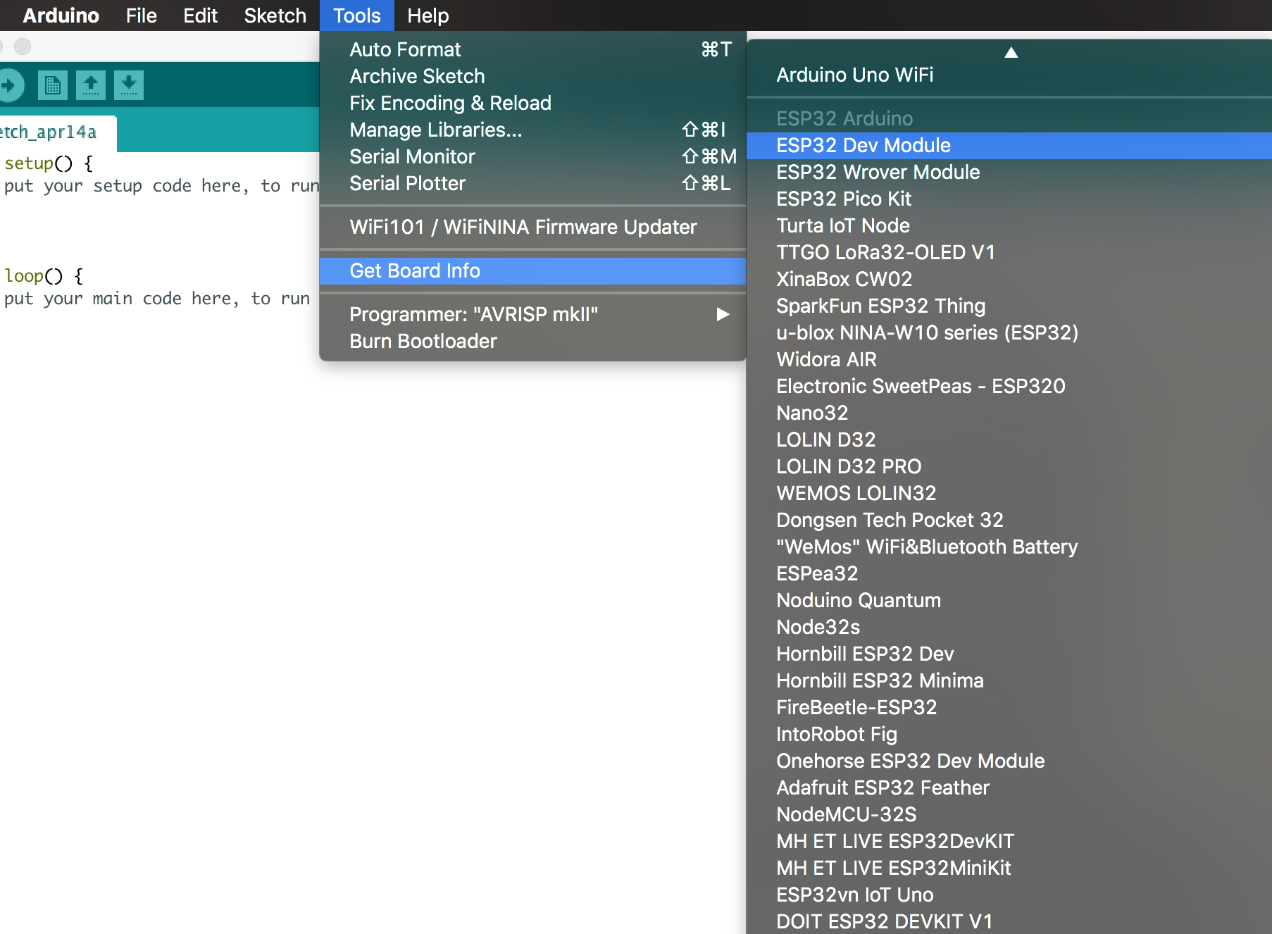
You should also be able to see quite a number of libraries installed alongside the core. The libraries are pretty extensive and should cover for most of the tasks you might need to do with the ESP32.
At this point, it is important to note that the ESP32 is completely different from the ESP8266, and the code for ESP8266 based projects will not work directly on the ESP32 until necessary modifications are made. Also, most of ESP8266 compatible libraries are not compatible with the ESP32 so quite a number of modification may be required. This is one of the downsides to building projects based on the ESP32.
With that done, we can now write the code for the demo project.
Code
The code for this tutorial is the blink example we are all familiar with.
Load the example by going to tools and selecting your ESP32 board (Mine is the DOIT ESP32 DEVKIT V1) then go to file > examples > built-in examples > basics > blink. This will open the blink example.
While I believe most people understand the blink code, to stick to the tradition, I will do a brief explanation.
We will make a slight modification to the code since we connected our LED to a pin different from the one on which the ESP32’s built-in LED is located. We start by declaring that pin.
int LED = 2;
Next is the void setup() function. All we need to do here is set the pin to which our led is connected as an output.
void setup()
{
  pinMode (LED, OUTPUT);
}
Lastly, the void loop function. Here we create lines of code to turn the LED on and off after certain intervals to create the blink effect.
void loop()
{
  digitalWrite(LED, HIGH);
  delay(1000);
  digitalWrite(LED_BUILTIN, LOW);
  delay(1000);
}
The complete code for the project is available below.
int LED = 2;
void setup()

{
   pinMode (LED, OUTPUT);
}

void loop()
{
  digitalWrite(LED, HIGH);
  delay(1000);
  digitalWrite(LED, LOW);
  delay(1000);
}
Demo
Connect the LED to the DOIT DEVKIT as illustrated in the schematics above and then connect the board to your computer and upload the code. You should see the LED blinking. It’s important to note that most ESP32 based boards have the “boot” button which must be pressed once the code is uploaded to the board.
That’s it for this tutorial guys. Over the next few tutorials, we will build more interesting and challenging projects using the WiFi and Bluetooth functionalities of the ESP32. Do reach out via the comment section if you have any question(s).


