H-Bridge for High Power Brushed DC Motor with Current Sense
- Rajkumar Sharma
- 367 Views
- medium
- Tested
- SKU: EL144112
- Quote Now
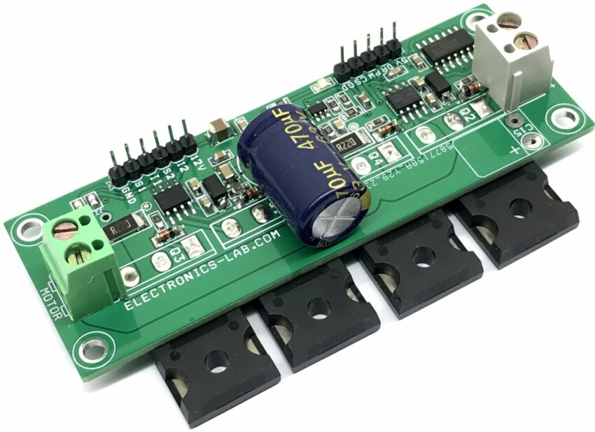
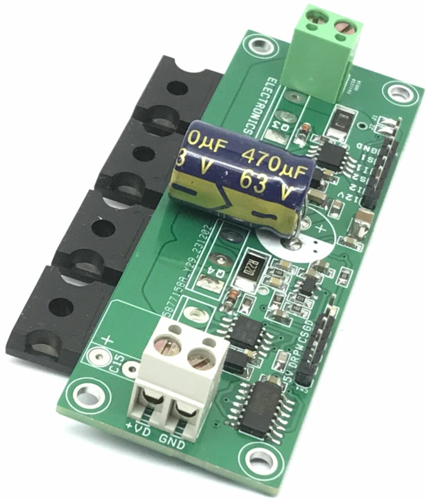
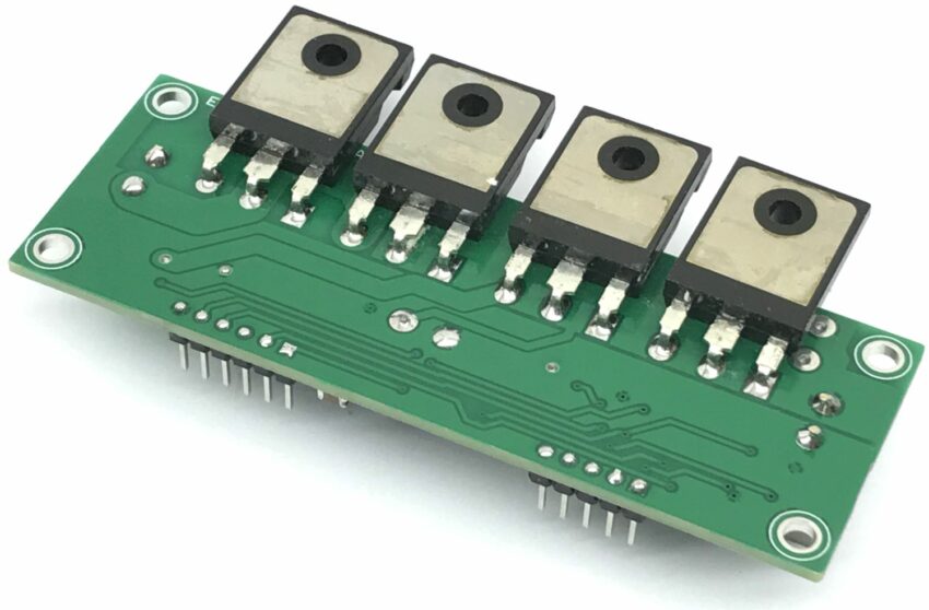
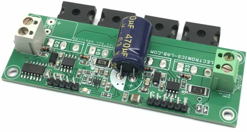
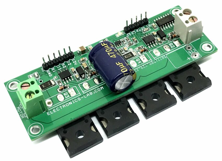
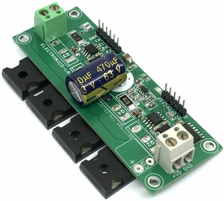
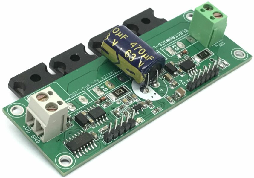
This H-bridge board is an easy-to-use brushed DC motor driver that can handle large-size motors such as wheelchair motors, and winch motors. An H-bridge is an electronic circuit that switches the polarity of a voltage applied to a load. The circuit is built using 4 x N-Channel MOSFETs, gate driver IR2104, and a logic circuit. The direction of rotation is dependent upon the polarity of the applied voltage. If you reverse the voltage, the direction of rotation reverses.
Features
- Power Supply Motor 12V to 50V DC
- Load Up to 10Amp Continues – Tested, Maximum 20A
- Gate Driver Power Supply 12V to 15V
- Logic/Current Sense Power Supply 5V
- PWM Frequency Up to 20Khz
- PWM Duty Cycle Input 95% to 5%
- On Board Current Circuit
- On Board Power LED (Gate Driver)
- 4 x 3 mm Mounting Holes
- PCB Dimensions 91.92 x 32.70 mm
PWM and Direction Control
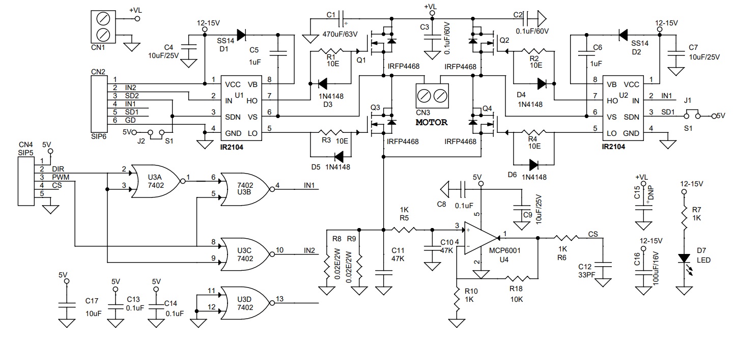
The project requires 2 signals to control the DC motor, a PWM for speed control and a DIR signal for direction control. The project is tested with a frequency up to 20KHz and a PWM duty cycle 95% to 5%. Both logic signals are TTL 5V compatible.
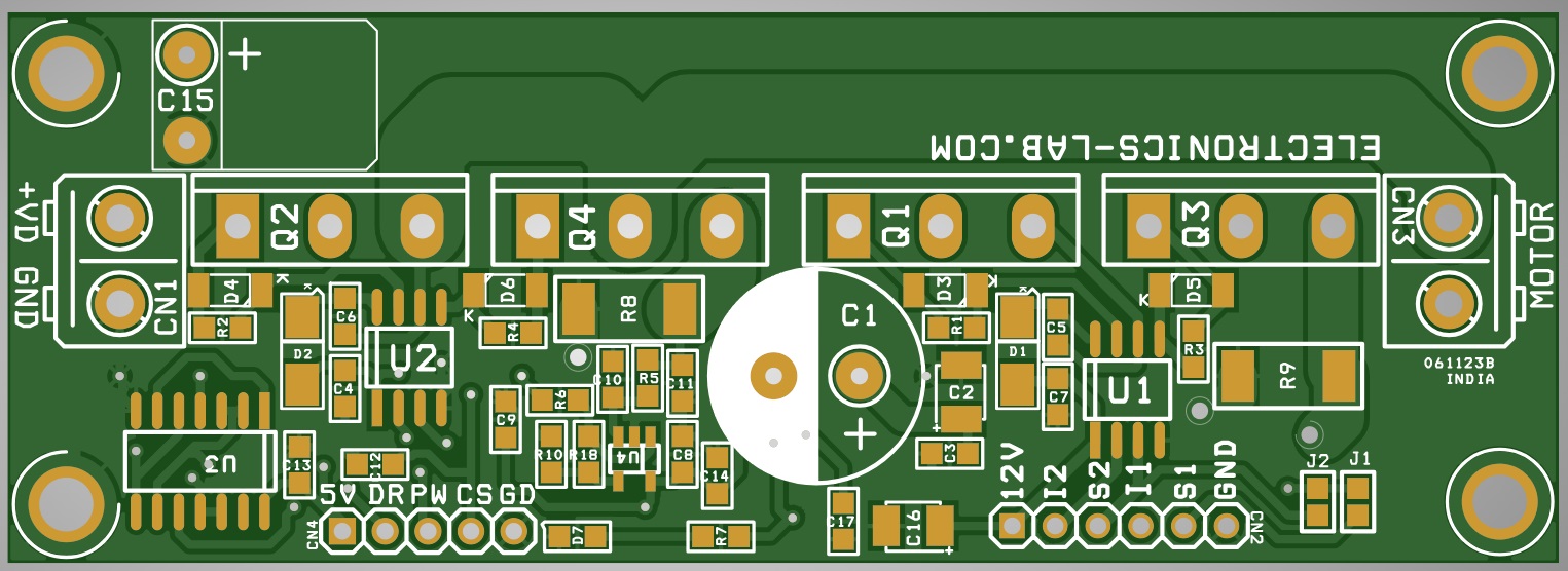
CN4: All Inputs are TTL 5V
- Pin 1 5V DC for U3 Chip
- Pin 2 Direction High or Low
- Pin 3 PWM Duty Cycle 95% to 5% Frequency up to 20Khz
- Pin 4 Current Sense Output
- Pin 5 GND
Direct Gate Driver Control: Shutdown, PWM/Logic
The project also can be controlled with direct logic signals applied to Gate driver chip IR2104, use connector CN2 for inputs, and don’t populate the U3 chip in this case.
CN2 Input Signals: All Input Signals are TTL 5V
- Pin 1 = VCC 12V Power for Gate Driver
- Pin 2 = IN2 PWM/Logic Input
- Pin 3 = Shutdown 2 (TTL Logic High=Enable)
- Pin 4 = IN1 PWM/Logic Input
- Pin 5 = Shutdown 1 (TTL Logic High=Enable)
- Pin 6 = GND
Current Sense
An optional current sense circuit can be used if required. The current sense circuit is built using OPAMP U4, which measures the current across shunt resistors R8 and R9 and provides current feedback at CN4 Pin 4. This signal can be used to detect the current flow, over current conditions etc. Current sense Output approx. 0.1V/A
Connection
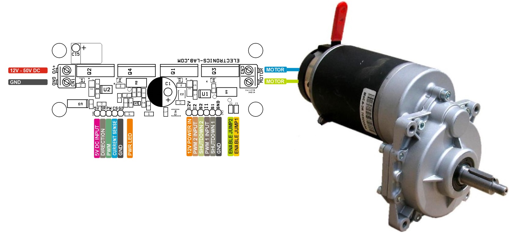
- CN1: Pin 1 = Motor Power Supply 12V to 50V DC, Pin 2 GND
- CN2: Pin 1 = Power for Gate driver 12 to 15V, Pin 2 IN2, Pin 3 Shutdown 3, Pin 4 IN1, Pin 5 = Shutdown 1, Pin 6 = GND
- CN3: Pin 1 = Motor, Pin 2 Motor
- CN4: Pin 1 = 5V DC for U3 and Current Sense Circuit, Pin 2 = Direction Input TTL5V (High/Low), Pin 3 = PWM Input Duty Cycle 95% to 5%, Pin 4 = Current Sense Output, Pin 5 = GND
- Jumper J1: Enable/Disable U2 (Jumper Closed = Enable)
- Jumper J2: Enable/Disable U1 (Jumper Closed = Enable)
- D7: Power LED
Schematic
Parts List
| NO. | QNTY. | REF. | DESC. | MANUFACTURER | SUPPLIER | SUPPLIER PART NO |
|---|---|---|---|---|---|---|
| 1 | 2 | CN1,CN3 | 2 PIN SCREW TERMINAL PITCH 5.08MM | PHOENIX | DIGIKEY | 277-1247-ND |
| 2 | 1 | CN2 | 6 PIN MALE HEADER PITCH 2.54MM | WURTH | DIGIKEY | 732-5319-ND |
| 3 | 1 | CN4 | 5 PIN MALE HEADER PITCH 2.54MM | WURTH | DIGIKEY | 732-5318-ND |
| 4 | 1 | C1 | 470uF/63V ELECTROLYTIC | PANASONIC | DIGIKEY | P10352-ND |
| 5 | 3 | C8,C13,C14 | 0.1uF/50V CERAMIC SMD SIZE 0805 | YAGEO/MURATA | DIGIKEY | |
| 6 | 2 | C2,C3 | 0.1uF/60V CERAMIC SMD SIZE 0805 | YAGEO/MURATA | DIGIKEY | |
| 7 | 4 | C4,C7,C9,C17 | 10uF/25V | YAGEO/MURATA | DIGIKEY | |
| 8 | 2 | C5,C6 | 1uF/25V CERAMIC SMD SIZE 0805 | YAGEO/MURATA | DIGIKEY | |
| 11 | 2 | C10,C11 | 47KPF CERAMIC SMD SIZE 0805 | YAGEO/MURATA | DIGIKEY | |
| 12 | 1 | C12 | 33PF/50V CERAMIC SMD SIZE 0805 | YAGEO/MURATA | DIGIKEY | |
| 13 | 1 | C15 | DNP | |||
| 14 | 1 | C16 | 100uF/16V CERAMIC SMD SIZE 1210 | TAIYO YUDEN | DIGIKEY | 587-5426-2-ND |
| 16 | 2 | D1,D2 | SS14 | TAIWAN SEMI | MOUSER | 821-SS14M2G |
| 17 | 4 | D3,D4,D5,D6 | 1N4148 | VISHAY | MOUSER | 78-1N4148WS-E3-18 |
| 18 | 1 | D7 | LED SMD SIZE 0805 | 475-1278-1-ND | DIGIKEY | OSRAM |
| 19 | 2 | J1,J2 | SOLDER JUMPER ON PCB | |||
| 20 | 4 | Q1,Q2,Q3,Q4 | IRFP4468 TO247 | INFINEON | DIGIKEY | IRFP4468PBF |
| 21 | 4 | R1,R2,R3,R4 | 10E 5% SMD SIZE 0805 | YAGEO/MURATA | DIGIKEY | |
| 22 | 4 | R5,R6,R7,R10 | 1K 5% SMD SIZE 0805 | YAGEO/MURATA | DIGIKEY | |
| 23 | 2 | R8,R9 | 0.02E/2W | DIGIKEY | ||
| 24 | 1 | R18 | 10K 5% SMD SIZE 0805 | YAGEO/MURATA | DIGIKEY | |
| 25 | 2 | U1,U2 | IR2104 SOIC8 | INFINEON | MOUSER | 942-IR2104STRPBF |
| 26 | 1 | U3 | SN7402 SOIC14 | TI | DIGIKEY | 296-1188-1-ND |
| 27 | 1 | U4 | MCP6001 SOT23-5 | MICROCHIP | DIGIKEY | MCP6001UT-I/OTCT-ND |
Connections


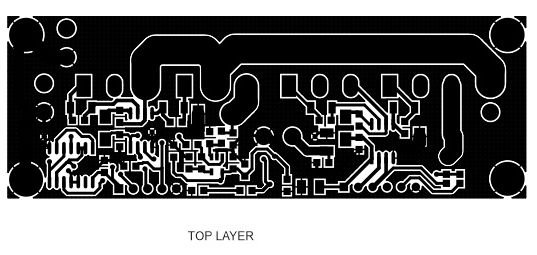
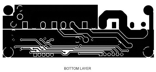


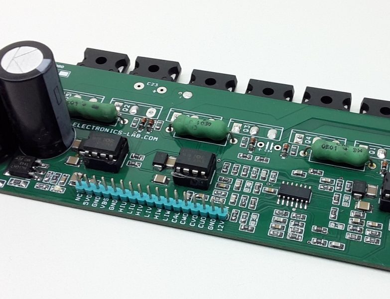
Looking at the DIR and PWM input signal and the logic designed, it seems to me that the duty cycle is mirrored (the output current at the H-bridge will be higher for a longer off-time duty cycle signal). Is that right?
Kind regards and thank you for sharing your designs.
F. Hdez.