Half-Bridge Driver Module – 48V/5A Load
- Rajkumar Sharma
- 14 Views
- easy
- Tested
- SKU: EL156743
- Quote Now
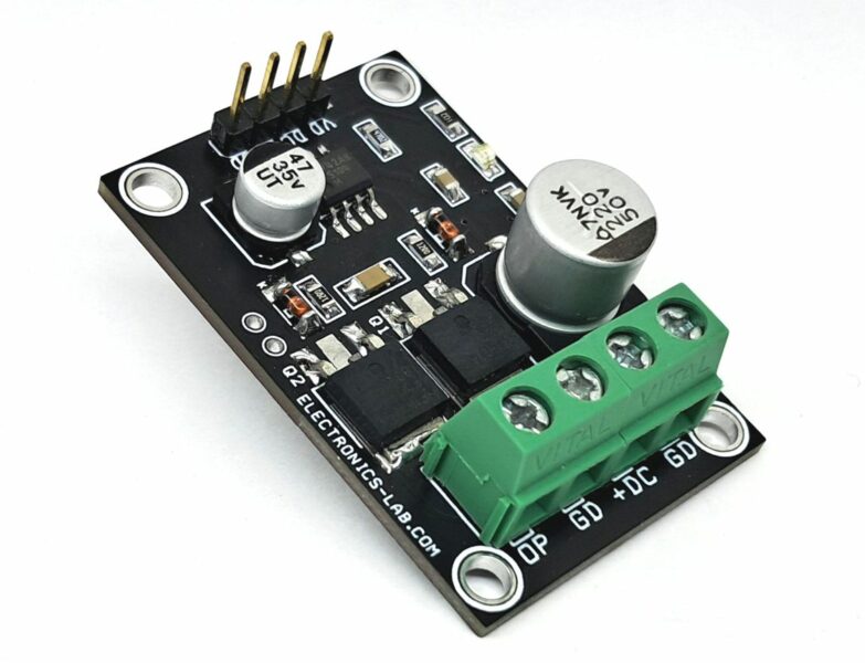
This Half-Bridge Driver Module is a low-voltage power management solution designed to drive a wide range of applications, including DC motors, DC-DC converters, and other inductive and resistive loads. The module is engineered to operate within a load supply voltage range of up to 48V DC and can handle a maximum load current of 5A, making it an ideal choice for various low-voltage power management applications. The design utilizes low-cost N-channel MOSFETs, specifically the IRFZ44, which provide a reliable and efficient switching performance. Barrier terminal blocks are employed for the load power input, while a header connector is used for the gate driver supply and input signal. The driver operates with a single PWM (Pulse Width Modulation) signal, and the SD (Shutdown) pin is enabled by default with an internal pull-up resistor. To disable the output, simply connect the SD pin to the ground. The board supports the use of either TO220 or TO247 MOSFETs, with two IRFZ44PBF MOSFETs (60V, 50A, 0.028 ohm) used in this particular design. This flexibility allows for easy adaptation to different application requirements.
Key Features
- Load supply: up to 48V DC (VL)
- Load current: up to 5A
- Gate Driver Power 12-15V (VCC)
- Low-cost N-channel MOSFETs (IRFZ44)
- Barrier Terminal blocks for load power input
- Header connector for gate driver supply and input signal
- Single PWM signal operation
- SD pin with internal pull-up resistor for default enable
- On Board Power LED
- UVLO off Positive Going Threshold 9V
- Supports TO220 or TO247 MOSFETs
- 4 x 4 mm PCB Mounting Holes
- PCB Dimensions 79.85 x 40.0 1mm
This module is suitable for use in a variety of applications, including:
- Motor control systems
- Power management systems
- DC-DC converters
- Low-voltage power supplies
- Industrial automation systems
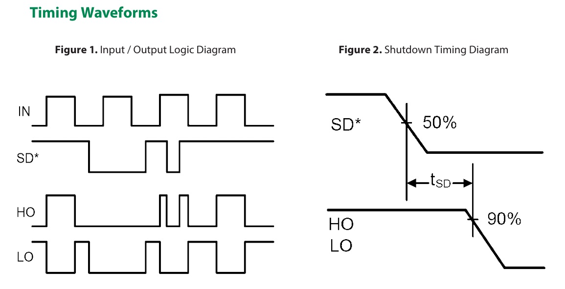
The LF2184N is a high-voltage, high-speed gate driver capable of driving N-channel MOSFETs and IGBTs in a half-bridge configuration. The high voltage technology enables the LF2184N’s high side to switch to 600V in a bootstrap operation. LF2184N logic inputs are compatible with standard TTL and CMOS levels (down to 3.3V) to interface easily with controlling devices. The driver outputs feature high pulse current buffers designed for minimum driver cross-conduction. LF2184N has a fixed internal dead time of 400ns (typical).
Connections
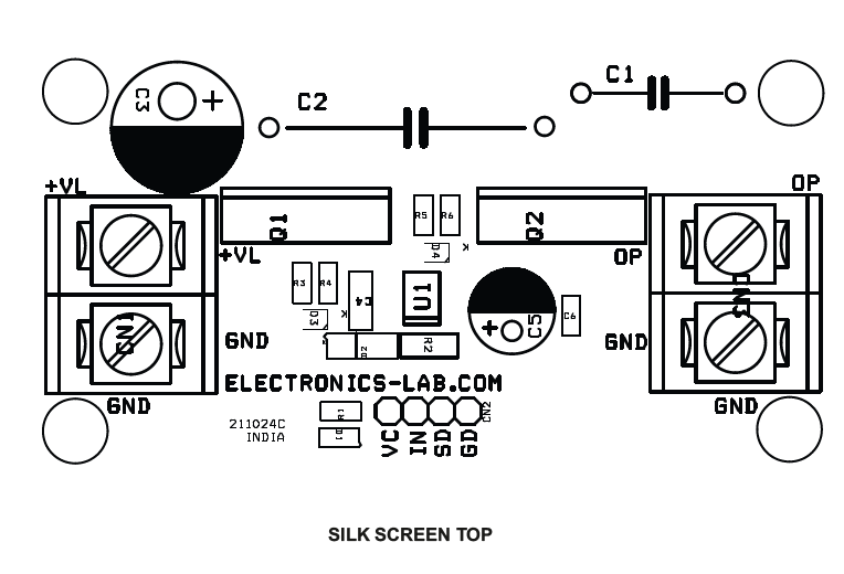
- CN1 Power: Pin 1 = +Load Power (VL) , Pin 2 = GND
- CN2: Pin 1 = VCC Gate Driver Power 12-15V DC, Pin 2 = PWM Input, Pin 3 = Shutdown, Pin 4 = GND
- D1: Power LED
Schematic
Parts List
| NO | QNTY | REF | DESC | MANUFACTURER | SUPPLIER | SUPPLIER PART NO |
|---|---|---|---|---|---|---|
| 1 | 2 | CN1,CN3 | 2 PIN BARRIER TERMINAL | TE CONNECTIVITY | A98481-ND | |
| 2 | 1 | CN2 | 4 PIN MALE HEADER PITCH 2.54MM | WURTH | 732-5317-ND | |
| 3 | 1 | C1 | 150nF/275VX2 OR 100V | PANASONIC | P14787-ND | |
| 4 | 1 | C2 | DNP | |||
| 5 | 1 | C3 | 470uF/63V ELECTROLYTIC DIA-12.5MM | RUBYCON | 1189-4027-ND | |
| 6 | 1 | C4 | 1uF/25V CERAMIC SMD SIZE 1206 | YAGEO/MURATA | ||
| 7 | 1 | C5 | 220uF/25V ELECTROLYTIC 8MM-DIA | WURTH | 732-8829-1-ND | |
| 8 | 1 | C6 | 100nF/50V CERAMIC SMD SIZE 0805 | YAGEO/MURATA | ||
| 9 | 1 | D1 | LED RED SMD SIZE 0805 | OSRAM | 475-1278-1-ND | |
| 10 | 1 | D2 | SS34 | MDD | 3372-SS34TR-ND | |
| 11 | 2 | D3,D4 | 1N4148 | DIOTEC | 4878-LL4148CT-ND | |
| 12 | 2 | Q1,Q2 | IRFZ44 TO220 | VISHAY | IRFZ44PBF-ND | |
| 13 | 1 | R1 | 2.2K 5% SMD SIZE 0805 | YAGEO/MURATA | ||
| 14 | 3 | R2,R4,R6 | 10E 5% SMD SIZE 1206 | YAGEO/MURATA | ||
| 15 | 2 | R3,R5 | 4.7E 5% SMD SIZE 0805 | YAGEO/MURATA | ||
| 16 | 1 | U1 | LF2184 SOIC8 | LITTELEFUSE | 5656-LF2184NTRCT-ND |
Connections
Block Diagram
Typical Application


