Hand Steadiness Tester
- Divam Gupta
- divamgupta@gmail.com
- 21.546 Views
- easy
- Non tested
Introduction
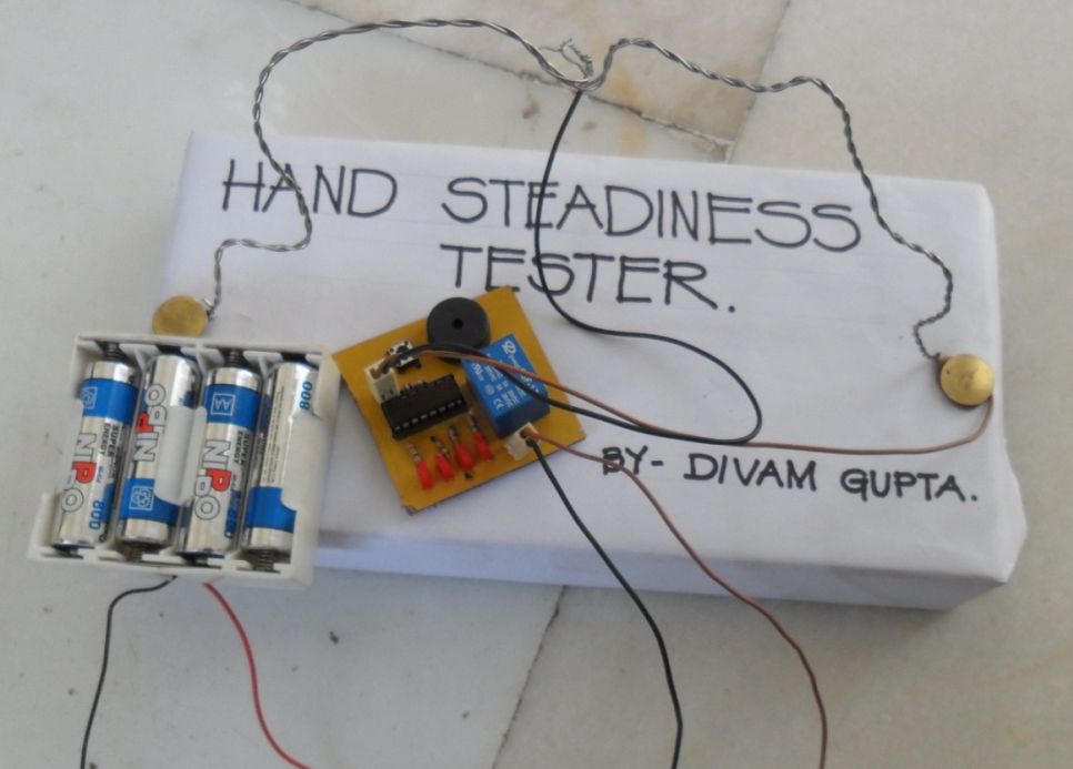
The Hand Steadiness Tester is a game which tests the steadiness of your hand. The player has to take the ring from one end to another end without touching it to the wire. In this the player gets 4 turns. If the player touches the wire 4 times he has to reset the game & start the whole game from the beginning.
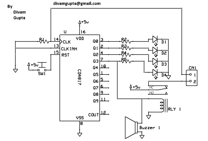
This project consists of IC 4017, a Buzzer, a Relay, some resistors, a Push button and 4 LEDs. There is also a PCB layout given. There are many types of Hand Steadiness Testers which are very simple. This New Hand Steadiness Tester is more advanced.
When the player touches the wire one time 1st LED turns on. When he touches 2nd time the 2nd LED turns on. When he touches 3rd time the 3rd LED turns on. When he touches 4th time the 4th LED turns on & the buzzer starts beeping. To stop the buzzer he has to push the reset button.
Schematic
Parts List
1. R1 10K
2. R2 R5 330 ohms
3. D1 D4 3v LEDs
4. IC1 IC 4017
5. SW1 Push Button
6. Buzzer 1 5v Buzzer
7. RLY 1 5v Relay
8. CN1 2 Pin Connector
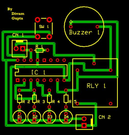
PCB
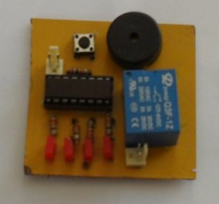
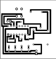
The circuit board is a Single Sided PCB with no SMT components (Very easy to make & solder). This is made in Express PCB. The PCB files are down below.
Explanation
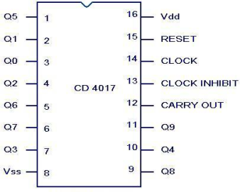
This is IC 4017. Q0 -Q3 are connected to LEDs through 330ohms resistors. Q3 is also connected to a buzzer & a relay. When we touch the wire with the ring, a positive current flows to pin 14. When the player touches the wire 4 times, the relay gets on; this breaks the contact between the ring and pin 14 of IC. So after that the buzzer keeps beeping. When we push the reset button, the IC resets and the buzzer, the LED & the relay gets off.
How to make it
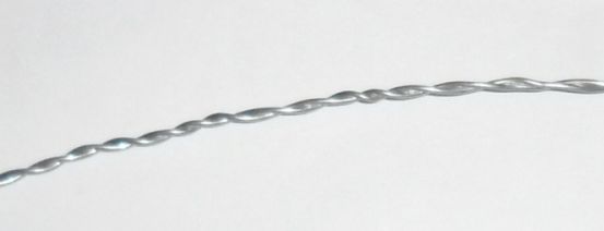
Then you need a wire. You should use a thick wire. Or you can take 2 wires and twist them to make it thick.
Then you need 2 thumb pins to attach the wire with the base.
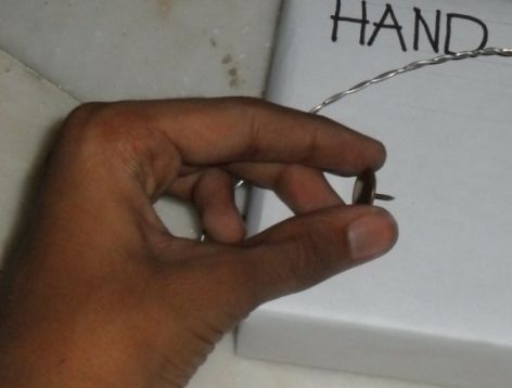
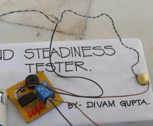
Now attach the both the ends of the wire to the board with the thumb pins.
Now you have to shape the wire in the way you want.
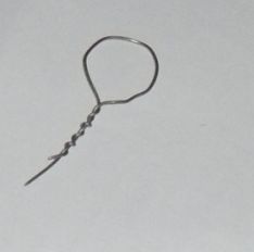
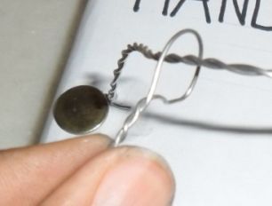
After that you need to make a ring. You can make it by a wire or you can use a key ring.
Now you need to attach the circuit. Take a connector and attach one wire to the ring and the other wire to the thumb pin.
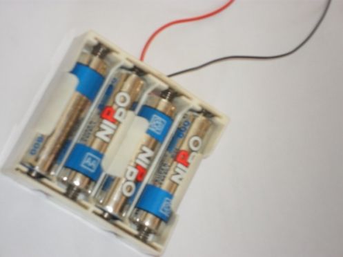
Now you just have to attach the battery. You can use a power supply circuit to give it exact 5 volts. You can also use 4 1.2 volts rechargeable cells.
Congratulations!! Your Advanced Hand Steadiness tester is ready.
If it doesn’t work
- Make sure that your connections are connected well.
- Make sure that your PCB is fabricated well.
- Make sure that batteries are working










Cool