High-Voltage Half-Bridge Board with Adjustable PWM Signal Generation
- Rajkumar Sharma
- 8 Views
- medium
- Tested
- SKU: EL156813
- Quote Now
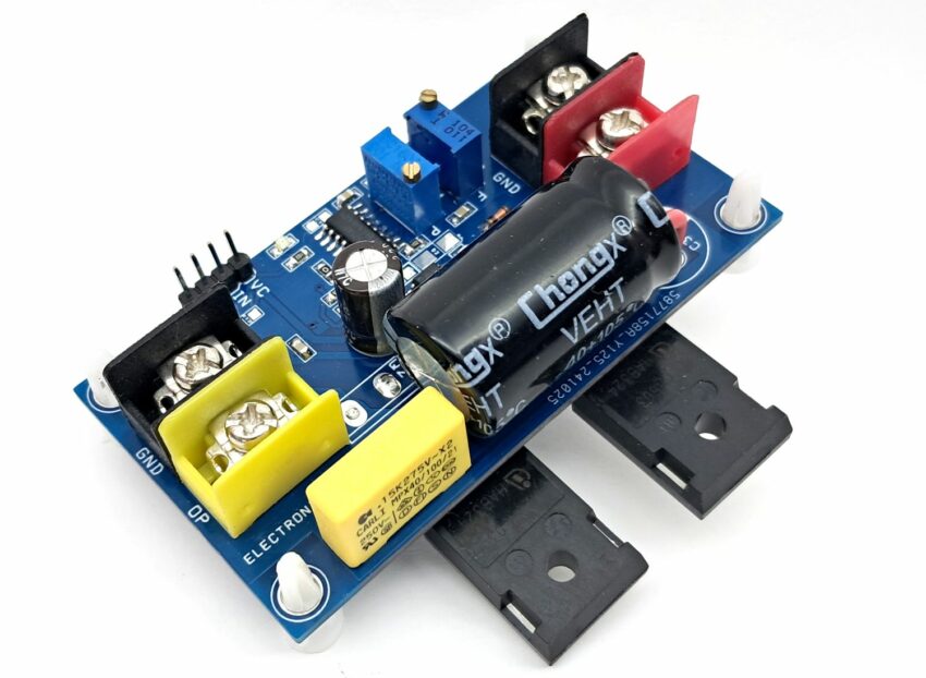
The high-voltage half-bridge board features a 2ED2184 half-bridge gate driver, 2 x IKW20N60H3FKSA1-ND IGBTs, and an SG3525 PWM signal generator. This board is designed to support bus supplies of up to 400V DC, PWM frequency up to 6.5Khz and adjustable duty cycle range 2% to 98% making it suitable for a wide range of applications, including:
- Refrigeration systems
- DC-DC converters
- AC to DC converters
- Electric vehicle (EV) chargers
- High-power LED and HID lighting systems
- Induction heating systems
Features
- Load Power Supply 400V DC
- Load Current 2-5Amps
- Power Supply Logic Gate Driver 12-15V DC
- On Board Power LED
- On Board Multiturn Potentiometer for Frequency/PWM Adjust
- PWM Signal Adjustable 2% to 98%
- Frequency Adjustable 500Hz to 6.5Khz
- Barrier Terminal Blocks for Load and Load Power Input
- On Board 100uF/450VDC Bus Capacitor
- PCB Mounting Holes 4 x 4 mm
- PCB Dimensions 79.53 x 43.50 mm
The onboard SG3525 chip provides adjustable frequency and PWM (Pulse Width Modulation) signal generation, allowing users to customize the output to their specific needs. The PWM signal is adjustable, with a duty cycle range of 2% to 98%. The frequency adjustment range is 500Hz to 6.5KHz, and can be fine-tuned using the multiturn trim pot PR1. Additionally, the SG3525 chip is capable of generating higher frequencies of up to 400KHz by altering the value of capacitor C8 (refer to the SG3525 datasheet for more information).
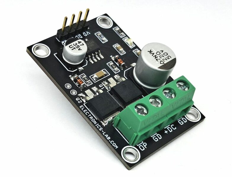
The 2ED2184 half-bridge gate driver is compatible with other suitable MOSFETs or IGBTs, depending on the voltage and load current requirements. Users should consider the bootstrap capacitor, DC bus capacitor, and gate resistors when selecting alternative MOSFETs or IGBTs. The project has been tested with a 100V DC supply and a 2A load.
SG3525 PWM Generator
The SG3525 chip generates a 5V PWM signal to the gate driver, which is adjustable using the multiturn trim pot P1. The PWM signal has a duty cycle range of 2% to 98%, and the frequency adjustment range is 500Hz to 6.5KHz using the multiturn trim pot PR1. By altering the value of capacitor C8, the SG3525 chip can generate higher frequencies of up to 400KHz (refer to the SG3525 datasheet for more information).
Connections
- CN1 Load Power: Pin1 = +VL, pin 2 = GND
- CN2: Not Used
- CN3 Load: Pin 1 = GND, Pin 2 = Output
- P1: PWM Adjust Multiturn potentiometer
- PR1: Frequency Adjust Multiturn potentiometer
- D1: Power LED
Schematic
Parts List
| NO | QNTY | REF | DESC. | MANUFACTURER | SUPPLIER | SUPPLIER PART NO |
|---|---|---|---|---|---|---|
| 1 | 2 | CN1,CN3 | 2 PIN BARRIER TERMINAL BLOCK 9.53MM | TE CONNECTIVITY | DIGIKEY | A98481-ND |
| 2 | 6 | R2,D2,CN2,C2,R12,R13 | DNP | |||
| 3 | 1 | C1 | 150nF/275VX2 | PANASONIC | DIGIKEY | P14787-ND |
| 4 | 1 | C3 | 100uF/450V 18MM-DIA/H32MM | RUBYCON | DIGIKEY | 1189-3221-ND |
| 5 | 1 | C4 | 4.7uF/35V CERAMIC SMD SIZE 1206 | YAGEO/MURATA | DIGIKEY | |
| 6 | 1 | C5 | 220uF/25V 6-8MM-DIA | RUBYCON | DIGIKEY | 1189-3698-3-ND |
| 7 | 1 | C6 | 2.2uF/25V CERAMIC SMD SIZE 0805 | YAGEO/MURATA | DIGIKEY | |
| 8 | 1 | C7 | DNP | |||
| 9 | 4 | C8,C9,C10,C11 | 100nF/25V CERAMIC SMD SIZE 0805 | YAGEO/MURATA | DIGIKEY | |
| 10 | 1 | D1 | LED RED SMD SIZE 0805 | OSRAM | DIGIKEY | 475-1278-1-ND |
| 11 | 2 | D3,D4 | 1N4148 SMD | MICRIOCHIP | DIGIKEY | 4878-LL4148CT-ND |
| 12 | 1 | PR1 | 100K MULTITURN | BOURNS INC | DIGIKEY | 3296Y-104LF-ND |
| 13 | 2 | P1,R7 | 10K MULTITURN | BOURNS INC | DIGIKEY | 3296W-103LF-ND |
| 14 | 2 | Q1,Q2 | IKW20N60H3FKSA1 | INFINEON | DIGIKEY | IKW20N60H3FKSA1-ND |
| 15 | 3 | R1,R9,R10 | 1K 5% SMD SIZE 0805 | YAGEO/MURATA | DIGIKEY | |
| 16 | 2 | R3,R5 | 1E 5% SMD SIZE 0805 | YAGEO/MURATA | DIGIKEY | |
| 17 | 2 | R4,R6 | 100E 5% SMD SIZE 0805 | YAGEO/MURATA | DIGIKEY | |
| 18 | 1 | R8 | 2.2K 5% SMD SIZE 0805 | YAGEO/MURATA | DIGIKEY | |
| 19 | 1 | R11 | 0E SMD SIZE 0805 | YAGEO/MURATA | DIGIKEY | |
| 20 | 1 | U1 | 2ED2184S06F SOIC8 | INFINEON | DIGIKEY | 448-2ED2184S06FXUMA1CT-ND |
| 21 | 1 | U2 | SG3525A SOIC16 | ST | DIGIKEY | 497-6479-1-ND |
Connections
Internal Block Diagram
Gate Driver Block Diagram


