How to use STONEtech STVC035WT-01 intelligent TFT LCD module with Arduino
- Emmanuel Odunlade
- emmaodunlade@gmail.com
- 6.657 Views
- Tested
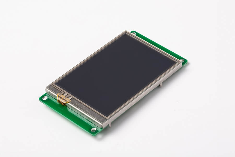
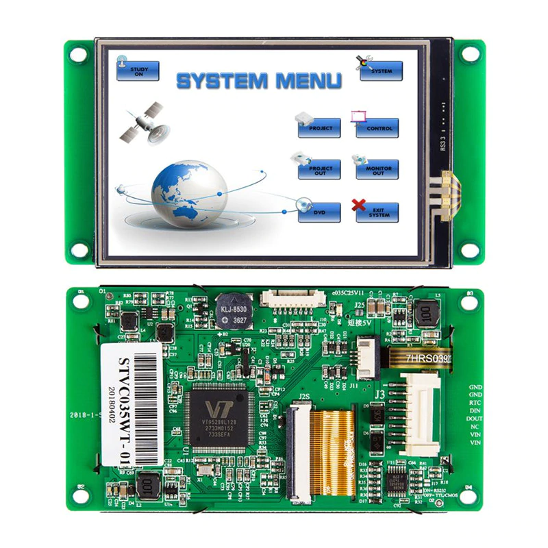
Displays have over time, emerged as one of the best ways to drive user interactions on any device. They make it easy to collect inputs and present information (outputs) to users in a graphical, easy to understand format. This usefulness has led to improvements in their quality, with improved resolution and low power features, but almost little has changed when it comes to the complexity of creating beautiful user interfaces for them. This is why the team at STONE Tech created the STVC035WT-01 intelligent Smart display which we will explore for today’s tutorial.
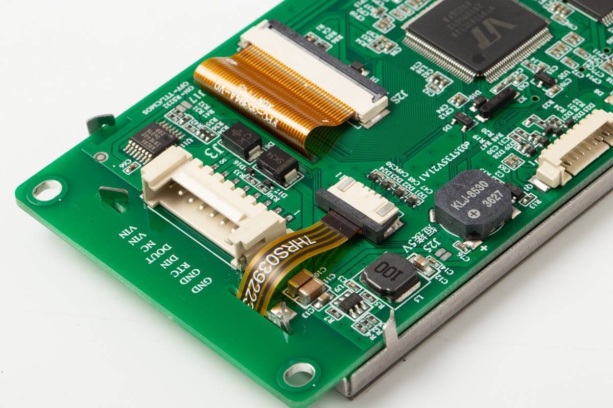
The STONE STVC035WT-01 display is a 16-bit, 3.5″ display with a 320×480 (RGB) resolution, has a 49.0 x 73.4mm viewing area, and pixel spacing of 0.1905mm×0.0635mm (H×V). The display is a Class A industry Panel with an Industry level 4 wire resistance based touch screen, all layered on an integrated CPU, driver, and flash memory with several communication interfaces to enable it to connect to data sources like microcontrollers. For communication with a microcontroller, the display supports serial communication protocols like UART/TTL, RS232, and RS485, ensuring it can communicate with any kind of microcontroller or industrial computers. The UART/TTL pin on the Display supports both 3.3v/5v logic level which adds another layer of ease to the use of the display as users need not worry about the need for logic level shifters when building using a microcontroller that operates on either of the voltage level mentioned.
A summary of the features and specification of the display are shown below:
- Cortex m4 CPU
- UART interface (RS232/RS485/TTL) ;
- 256-byte register;
- 128 kb variable memory;
- 128 MB flash memory, expandable to 1 GB;
- GUI design software;
- A customized command set;
- 8-channel curve trend chart memory;
- extremely fast variable display response speed;
- A single-page supports up to 128 display variables;
- Integrated real-time clock RTC,
- Touch buzzer sound function;
- Support software 90 degrees, 180 degrees, 270 degrees screen rotation, adjust the appropriate visual Angle;
One of the major benefits of using this display is its compatibility with the STONE TOOL GUI Designer which allows the development of User Interfaces in a fast and easy manner.
To demonstrate the capabilities of the display, we will build a heart rate monitor using an Arduino Uno with the MAX30100 pulse oximetry and heart rate sensor. The Arduino will serve as the brain of the project and perform the simple task of obtaining the heart rate and blood oxygen data from the MAX30100, displaying it on the screen.
At the end of this tutorial, you would know how to interface Arduino boards with the STONETech displays, and also how to interface sensors like the MAX30100 with the Arduino.
Required Components
The following components are required to build this project;
- Arduino Uno
- STVC035WT-01 (or any other STONE Tech display)
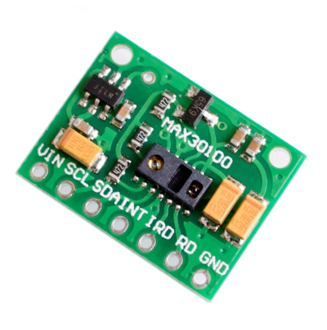
- MAX30100 Pulse Optometry sensor
- MAX3232
- Bread Board
- Jumper Wire
- Power Bank/Battery with a 9v Jack
Creating the GUI
There are 2 major steps associated with the development of devices using any of the STONEtech displays:
- Creating the GUI using the STONE GUI Design Tool and exporting the GUI to the display.
- Connecting the display to the microcontroller and writing the code to integrate the microcontroller with the display.
Our development process for today’s project will follow this outline. We will first create the GUI for the project after which we will proceed to write the firmware to interface the microcontroller with the display.
1. Creating the GUI using the STONE TOOL GUI Designer
There are two major ways of creating a GUI. One is to create the GUI using only the elements (buttons, text boxes, etc) that are available within the GUI Design tool, while the second is to create a mockup image using image editing tools like Photoshop/Paint.NET, import the image into the GUI Desing tool software and place the GUI design elements on the image. For this tutorial, we will go with the second option as it allows more flexibility and gives room for the development of truly beautiful GUIs.
As mentioned during the introduction, today’s tutorial will focus on creating a heart rate and Oxygen-level monitoring system using the display and to get things started, we create the GUI image (shown below) using Photoshop.
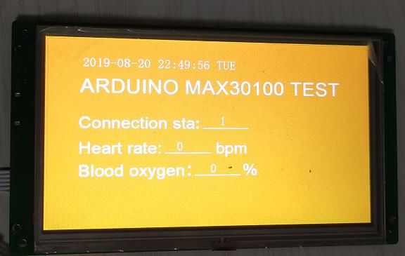
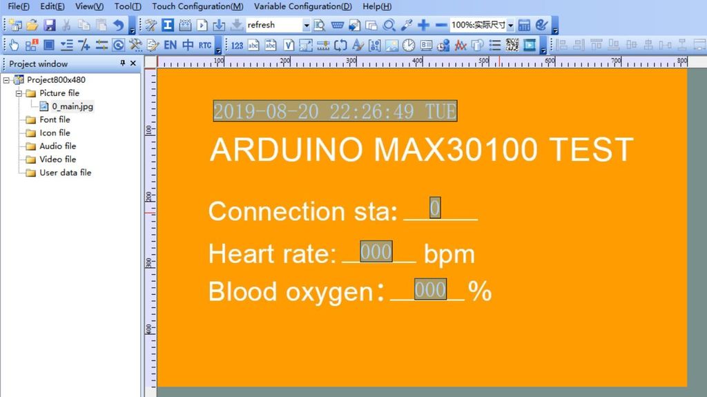
The design is quite simple, we illustrate label elements to hold the date, the project title, and the values from the microcontroller. The values from the microcontroller include; the status of the connection between the microcontroller and the display, the heart rate, and the oxygen levels.
With the GUI Image done, we then proceed to import it into the STONE TECH GUI tool. This obviously mean we need to install the STONE TOOL first, so head over to the STONE Tool GUI Designer page and download it. The STONE TOOL software requires no installation and it can be directly opened and run by decompression on your computer.
It should be noted that while compatibility with other OS is currently being considered, the current version of the software only supports Windows 8 and 10 operating systems.
Follow the steps below to create the GUI.
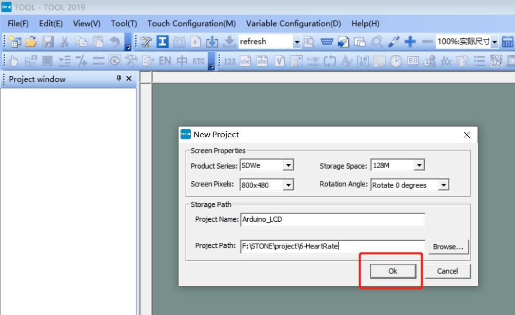
1. With the software downloaded on your computer, launch it and go to File>New Project. This will launch the “New Project dialog box ” where you will be expected to fill in the details of your display, set the storage path, and the name of your project. Since we will use the STVC035WT-01 display which has a resolution of 320*480 and a default flash space size of 128Mbyte (expandable to 1024MByte), I have entered its details as shown in the image below. If you are using any of the other StoneTech displays, you will need to enter the details of that display instead.
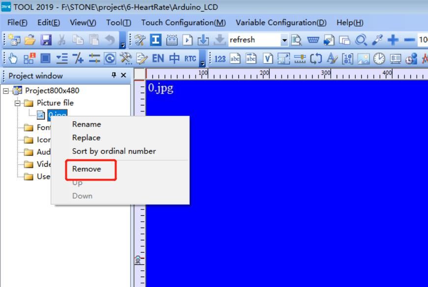
2. Next, on the left side of your screen, you will see the project tree (under the project window) with its assets. Expand the Picture file, and delete the 0.jpg image inside it by right-clicking on it, and selecting “Remove”. For every new project, the 0.jpg file is always created as the default background for your UI, since we will use our background (the one we designed with photoshop), we can delete it.
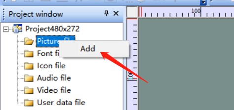
3. Next, we need to add the background we designed with photoshop into the picture file. Right-Click on the “Picture” directory and select “Add”. This will open a dialog box for you to navigate to where the JPG version of our photoshop images is stored.
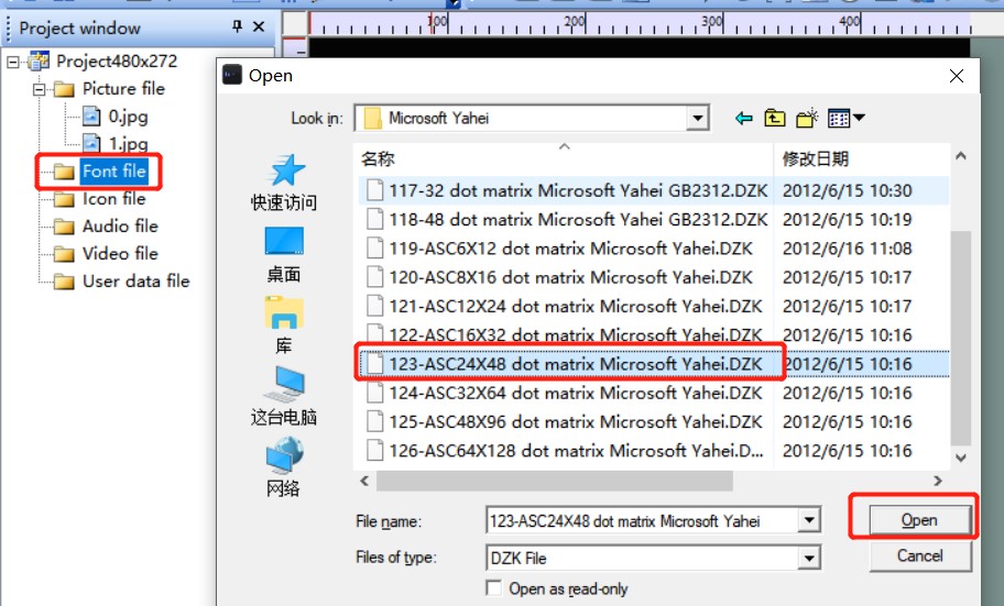
4. Next, we add fonts to the project’s assets to determine how texts appear on the display. Right-click the “Font” file, and select the appropriate font to add to the project. For this tutorial, we will use the ASCII 24 by 48 font. With that done we are now ready to begin adding the GUI elements.
5. We will only use the “Text Display” GUI element since the display is only meant to display data from the MAX30100. The text display elements are capable of holding texts that can be changed programmatically by updating the data stored in their memory addresses. Add text displays on the lines as highlighted in the image below. Also, create a text display for the day-time section at the top of the display image to help users note the date/time each reading was observed.
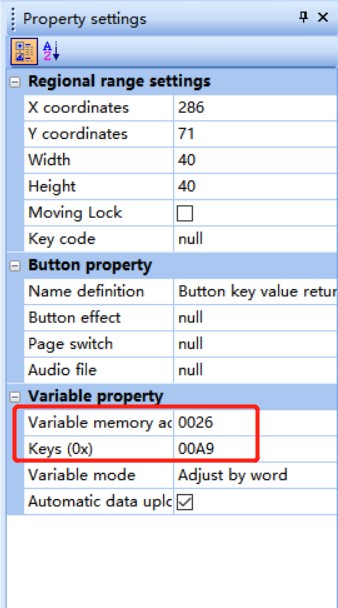
6. Next, we set the properties of the text displays especially their memory addresses. The properties of each GUI element will be available on the right-hand side of your PC screen after clicking on the element. Note the memory address down as it will play an important role later.
7. With all of these done, we compile the GUI and upload it to the screen. To do this, click on button 1 in the image below to Compile the GUI design and click on button 2 to upload the GUI to your display.
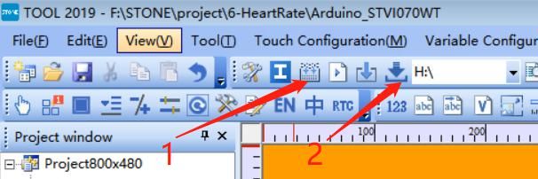
Uploading the GUI display requires you either connect the display directly to your computer or you put the GUI on a flash drive and plug the flash drive into the USB port of the display. Because of the little complexity associated with the second option, we will be going with it.
Plug the USB flash drive into the computer then click the “Download to u-disk” button on the STONE GUI TOOL. With the “download to u-disk” process complete, pull out the USB flash disk, insert it into the USB interface of the display module and wait for the completion of the upgrade. When the upgrade is completed, there will be a prompt sound.
With the GUI uploaded to the display, we can now connect the display and other components and write the Arduino code to publish data to it.
Schematics
Connect the display and the MAX30100 to the Arduino as shown in the image below.
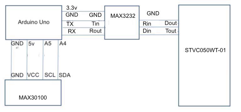
The model of the STONE display being used for this tutorial communicates via RS232, as such, to be able to interface the display with the Arduino, we have to connect it through a MAX3232 chip. This extra requirement can be avoided by using one of the STONE displays with a TTL interface.
To make the schematics easier to follow, a pin-to-pin map showing how each of the components connects, one to the other, is provided below.
STVC035WT-01 – Max3232
Din - Rin
Tout - Din
GND - GND
Max3232 – Arduino
Rout - RxD
Tin - TxD
GND - GND
VCC- 5v
MAX30100 – Arduino
SDA - A4
SCL - A5
GND - GND
VCC- 5v
Go over the connections once again to be sure everything is properly connected. With this done we can now proceed to the Arduino code to send commands and data to the LCD.
Arduino Code
The idea behind the Arduino code is to condition the data from the MAX30100 and create a pipeline for the data to be sent to the LCD display.
Due to the simplicity embedded in the design of STONETECH displays, the microcontroller’s interaction with any of the GUI components is usually via the “memory address” of each component. for instance, to send a message to the display from the microcontroller (the Arduino in this case), the message has to be published to the memory address of the GUI Component (in this case, the text-display component). The same holds for GUI Components that are meant to send data to the microcontroller, as the microcontroller has to poll their memory address to obtain information from them. As a result of these, we need to obtain the memory address of all the GUI components before proceeding. For each GUI component, the memory address is usually listed among the properties of the component, under the property toolbar, at the right-hand side of the STONE TOOL interface.
While mine may be different from yours, the memory address of the text displays is provided below.
- Connection sta : 0x0008
- Heart rate : 0x0001
- Blood oxygen : 0x0005
With this obtained, we can now proceed to write the code for the project. One of the good things about using the STONETech displays is the fact that you don’t need a library to write code for them because of their simplicity, but since we will use serial communication, we will use the software serial library to avoid having to use the hardware serial port on the Arduino Uno. To interface with the MAX30100, we will also need to install the MAX30100 library. The Max30100 library can be installed using the Arduino Library Manager or by downloading it from the attached link and installing manually by extracting the file, copying its content and pasting it in the Arduino libraries folder. The software serial library comes pre-installed with the Arduino IDE.
>With the libraries installed, we now have all we need to write the Arduino Code. As usual, I will do a brief explanation and attach the complete version of the code under the download section.
We start the code by including the libraries we will use. The Wire.h library is added to satisfy the I2C requirements of the Max30100 library.
#include <Wire.h>
#include <SoftwareSerial.h>
#include "MAX30100_PulseOximeter.h"
Next, we create an instance of the software serial and MAX30100 libraries.
SoftwareSerial screenserial(10, 11); // RX, TX
PulseOximeter pox;
Next, we create variable names to hold the memory address of the three GUI elements we will use for data display.
#define Heart_dis_addr 0x01
#define Sop2_dis_addr 0x05
#define connect_sta_addr 0x08
Next, we provide the customized commands that will be sent to the screen to store data in the memory address. The commands are the same for all the elements with the only difference being the memory address.
unsigned char heart_rate_send[8]= {0xA5, 0x5A, 0x05, 0x82,\
0x00, Heart_dis_addr, 0x00, 0x00};
unsigned char Sop2_send[8]= {0xA5, 0x5A, 0x05, 0x82, 0x00, \
Sop2_dis_addr, 0x00, 0x00};
unsigned char connect_sta_send[8]={0xA5, 0x5A, 0x05, 0x82, 0x00, \
connect_sta_addr,0x00, 0x00};
Next, we specify the variables; Reporting_Period_MS and tsLastReport, which will be used to determine when the sensor should be refreshed. With this done, we then move to the void setup() function.
#define REPORTING_PERIOD_MS 1000

uint32_t tsLastReport = 0;
We start the function by initializing serial communications between the screen and the microcontroller setting the baud rate to 115200. We also initialize hardware serial communication so we can use the serial monitor on the Arduino IDE for debugging purposes.
void setup()

{
  screenserial.begin(115200);
  Serial.begin(9600);
Next, we initialize the MAX30100 and send the status of the initialization to the display. If the initialization fails, 0x00 meaning 0 is sent to the display, but if successful, 0x01 meaning 1 is sent to it.
Serial.print("Initializing pulse oximeter..");
  Initialize the PulseOximeter instance
  if (!pox.begin())
  {
    Serial.println("FAILED");
    connect_sta_send[7]=0x00;
    screenserial.write(connect_sta_send,8);

    for(;;);

  }
  else
  {
    connect_sta_send[7]=0x01;
    screenserial.write(connect_sta_send,8);
    Serial.println("SUCCESS");

  }
To wrap up the void setup() function, we increase the current of the IR LED on the Max30100 beyond the default 50mA. With this done, we move to the void loop() function.
 // The default current for the IR LED is 50mA and it could be changedby uncommenting the following line. Check MAX30100_Registers.h for all theavailable options.
  pox.setIRLedCurrent(MAX30100_LED_CURR_7_6MA);
}
We start the void loop() function by calling for updated readings, after which we check if the reporting period has elapsed. If the reporting period has elapsed, it means we need to take new measurements, so we call the pox.getHeartRate and pox.getSp02 commands to get new heart rate and oxygen levels. These new readings are displayed on the serial monitor and also sent to the display.
void loop()
{
  // Make sure to call update as fast as possible
  pox.update();
  // Asynchronously dump heart rate and oxidation levels to the serial
  // For both, a value of 0 means "invalid"
  if (millis() - tsLastReport > REPORTING_PERIOD_MS)
  {
    Serial.print("Heart rate:");
    Serial.print(pox.getHeartRate());
    Serial.print("bpm / SpO2:");
    Serial.print(pox.getSpO2());
    Serial.println("%");
    heart_rate_send[7]=(uint32_t)pox.getHeartRate();
    screenserial.write(heart_rate_send,8);// send heart rate to display
    Sop2_send[7]=pox.getSpO2();
    screenserial.write(Sop2_send,8);// send oxygen level to display.
    tsLastReport = millis();

  }

}
The complete code for the project is provided below and also attached under the download section of the tutorial.
#include <Wire.h>
#include <SoftwareSerial.h>
#include "MAX30100_PulseOximeter.h"


SoftwareSerial screenserial(10, 11); // RX, TX
PulseOximeter pox;


#define Heart_dis_addr 0x01
#define Sop2_dis_addr 0x05
#define connect_sta_addr 0x08
unsigned char heart_rate_send[8]= {0xA5, 0x5A, 0x05, 0x82,\
0x00, Heart_dis_addr, 0x00, 0x00};
unsigned char Sop2_send[8]= {0xA5, 0x5A, 0x05, 0x82, 0x00, \
Sop2_dis_addr, 0x00, 0x00};
unsigned char connect_sta_send[8]={0xA5, 0x5A, 0x05, 0x82, 0x00, \
connect_sta_addr,0x00, 0x00};

#define REPORTING_PERIOD_MS 1000

uint32_t tsLastReport = 0;

void setup()

{
  screenserial.begin(115200);
  Serial.begin(9600);
  Serial.print("Initializing pulse oximeter..");
  Initialize the PulseOximeter instance
  if (!pox.begin())
  {
    Serial.println("FAILED");
    connect_sta_send[7]=0x00;
    screenserial.write(connect_sta_send,8);

    for(;;);

  }
  else
  {
    connect_sta_send[7]=0x01;
    screenserial.write(connect_sta_send,8);
    Serial.println("SUCCESS");

  }
  // The default current for the IR LED is 50mA and it could be changedby uncommenting the following line. Check MAX30100_Registers.h for all theavailable options.
  pox.setIRLedCurrent(MAX30100_LED_CURR_7_6MA);
}

void loop()
{
  // Make sure to call update as fast as possible
  pox.update();
  // Asynchronously dump heart rate and oxidation levels to the serial
  // For both, a value of 0 means "invalid"
  if (millis() - tsLastReport > REPORTING_PERIOD_MS)
  {
    Serial.print("Heart rate:");
    Serial.print(pox.getHeartRate());
    Serial.print("bpm / SpO2:");
    Serial.print(pox.getSpO2());
    Serial.println("%");
    heart_rate_send[7]=(uint32_t)pox.getHeartRate();
    screenserial.write(heart_rate_send,8);// send heart rate to display
    Sop2_send[7]=pox.getSpO2();
    screenserial.write(Sop2_send,8);// send oxygen level to display.
    tsLastReport = millis();

  }

}
Demo
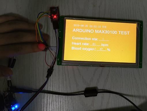
With the code complete, connect your Arduino board to your computer and upload the code to your setup. Place a finger on the Max30100 and after a while, you should see the live pulse rate and oxygen levels appear on the display as shown in the image below.
While this project only demonstrates less than 35% of the capabilities of the STONE TECH display, it provides a good foundation for you to build amazing projects. As an engineer, the key benefit of the display to me is the ease of use both in the creation of the GUI and also the development of the code to tie it together with a microcontroller. The fact that the display doesn’t require any library makes it perfect for use with any language and any microcontroller with serial port access.
The quality, size ανδ variety of the STONE TECH displays makes them perfect for HMI Applications and one of my next projects will be a Home Automation Panel using one of the STONETECH displays.
Τhat’s it for this tutorial guys. Feel free to reach out to me via the comment section if you have any difficulties with recreating this project.
Resources
- Introductory videos: https://www.stoneitech.com/support/download/video
- Intro Blog: https://www.electronics-lab.com/design-custom-ui-with-stone-tech-intelligent-tft-lcd-module/
- User Manual: https://www.stoneitech.com/support/download/user-manual
- App Note: https://www.stoneitech.com/application/application-note
- Datasheet: https://www.stoneitech.com/support/download/data-sheet
- Product Page: https://www.stoneitech.com/product/by-application/civil-type/touch-display-screens.html
- Software: https://www.stoneitech.com/support/download/software




Great tutorial.I consulted the website and placed an order for stvc043wt-01 4 inch products.Waiting for delivery.
I used Stone’s software, which saved me a lot of development time.The aftermarket is also great.
This tutorial looks pretty good.I want to see more articles of this quality.
That’s great.I also want to know the details of how it connects to Arduino.I bought a piece of this type of screen at https://www.stoneitech.com/product/by-application/industrial-type/stvi070wt-01.html.There's a problem with the transfer plate.
Great tutorial