HV Nixie DC-DC Switching Power Supply
Nixie tubes need about ~180Vdc to light up and thus on most devices, a DC-DC converter is needed. Here we designed a simple DC-DC switching regulator capable of powering most of Nixie tubes. The board accepts 12Vdc input and gives an output of 150-250Vdc. The board is heavily inspired by Nick de Smith’s design.
Description
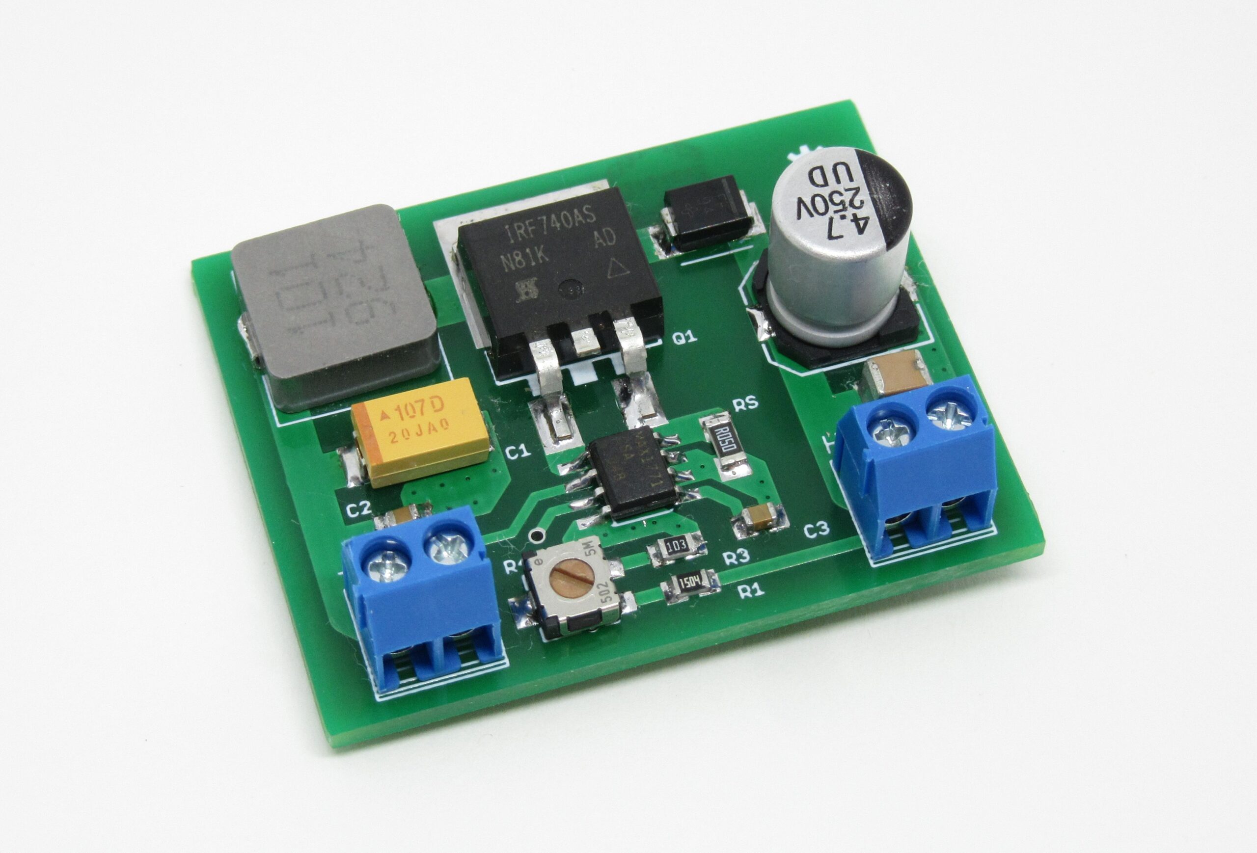
The module is based on the MAX1771 Step-Up DC-DC Controller. The controller works up to 300kHz switching frequency and that allows the usage of miniature surface mount components. In the default configuration, it accepts an input voltage from 2V to Vout and outputs 12V, but in this module, the output voltage is selected using the onboard potentiometer and it’s in the range 150-250Vdc. The maximum output current is 50mA @ 180Vdc.
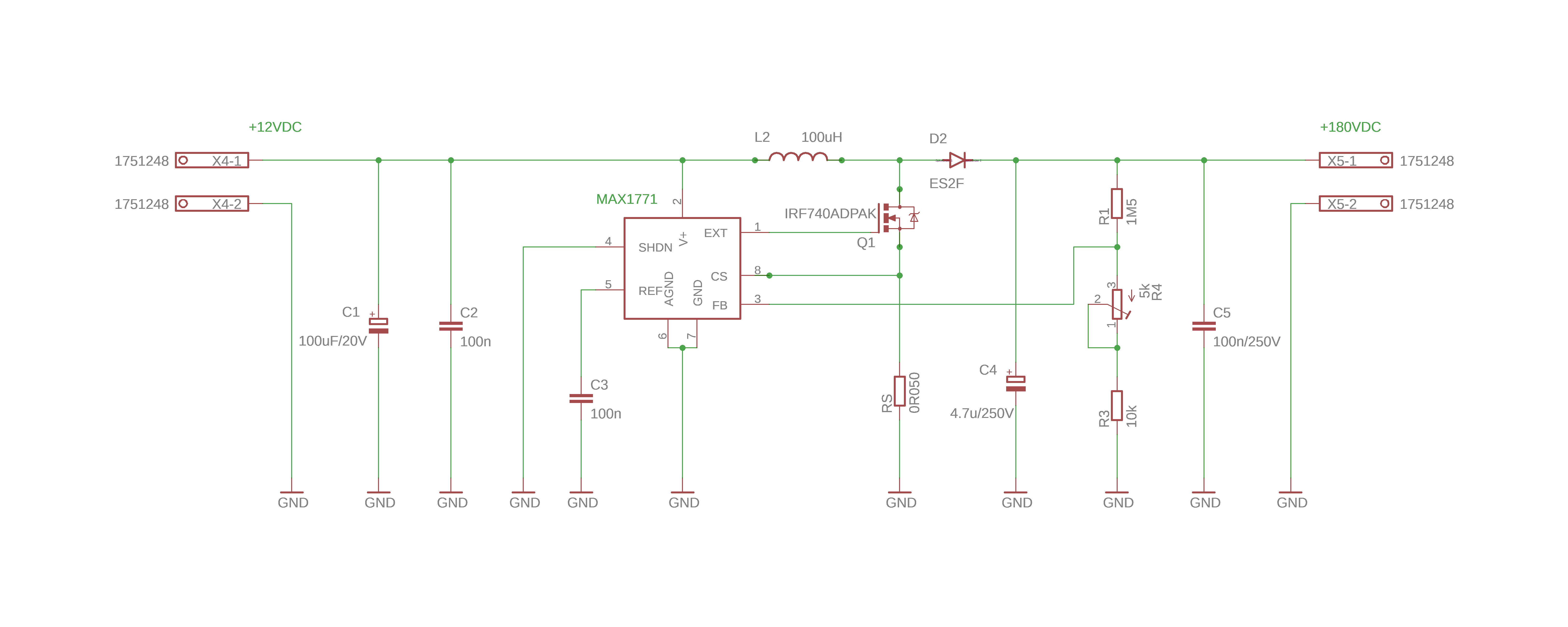
The MAX1771 is driving an external N-channel MOSFET (IRF740) and with the help of the inductor and a fast diode, high voltage is produced.
MOSFET has to be low RDSon, the diode has to be fast Mttr, typically < 50nS, and capacitors have to be low ESR type to have good efficiency.
Schematic
Parts List
| Part | Value | LCSC.com |
|---|---|---|
| R1 | 1.5M - 0805 SMD | C118025 |
| R3 | 10k 0805 | C269724 |
| R4 | 5k trimmer SMD | C128557 |
| Rs | 0.05 Ohm - 0805 SMD | C149662 |
| C1 | 100uF Tantalium SMD | C122302 |
| C2, C3 | 100nF - 0805 SMD | C396718 |
| C4 | 4.7uF / 250V SMD | C88702 |
| C5 | 100nF / 250V SMD 1210 | C52020 |
| IC | MAX1771 SO-8 | C407903 |
| L1 | 100uH / 2.5 A | C2962892 |
| Q1 | IRF740 D2PAK (TO-263-2) | C39238 |
| D2 | ES2F-E3, ES2GB | C145321, C2844160 |
| X1, X2 | Screw Terminal - P=3.5mm | C474892 |
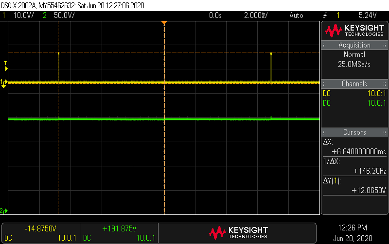
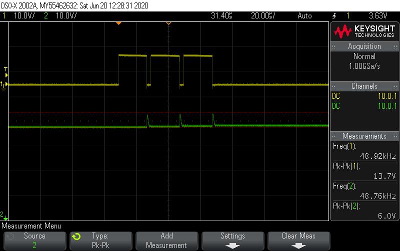
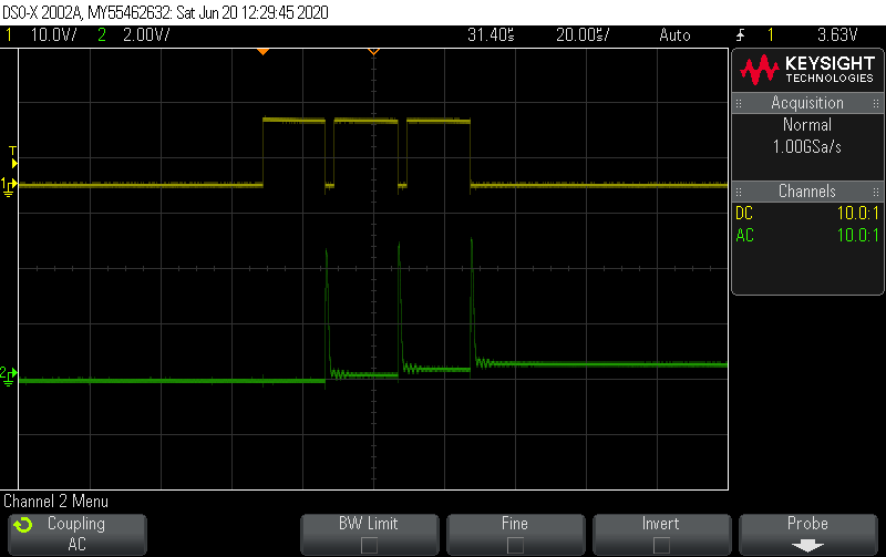
Oscilloscope Measurements
Efficiency
The module’s efficiency is calculated for two output currents (50mA and 25mA) at 180Vdc voltage output and 12V input. In the first case, the Pout = 8.1W while the Pin=10.96W, so efficiency is calculated at 73.9%. In the second case, the Pout = 4.1W while the Pin=5.52W, so efficiency is calculated at 74.2%. We see that for lower currents efficiency is a little greater than for the maximum current of 50mA.
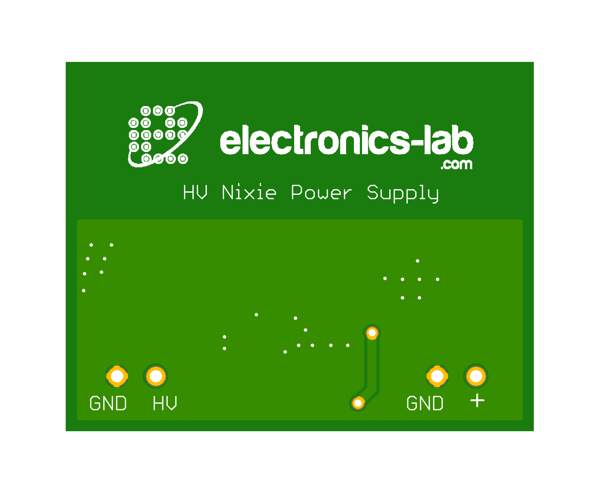
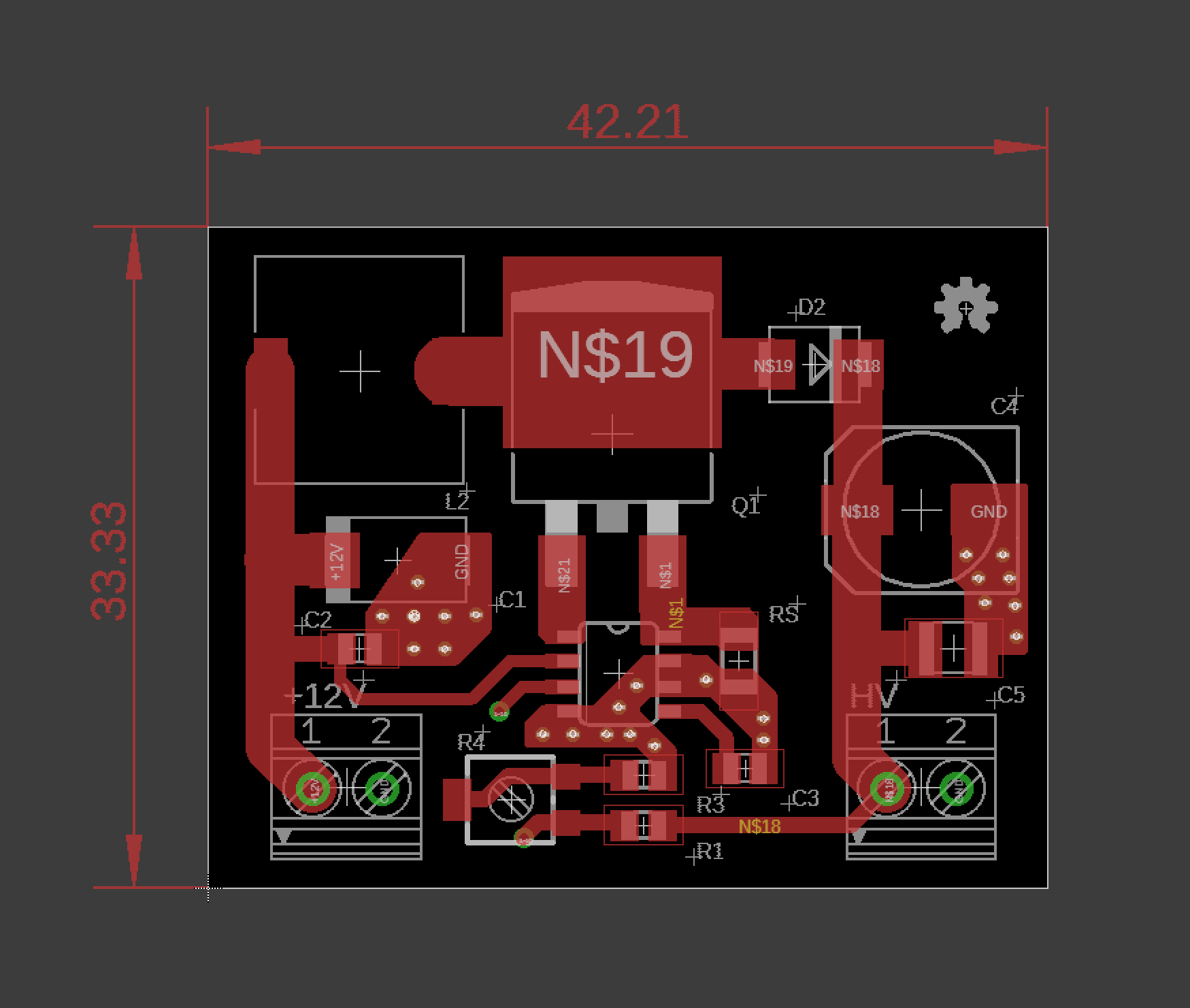
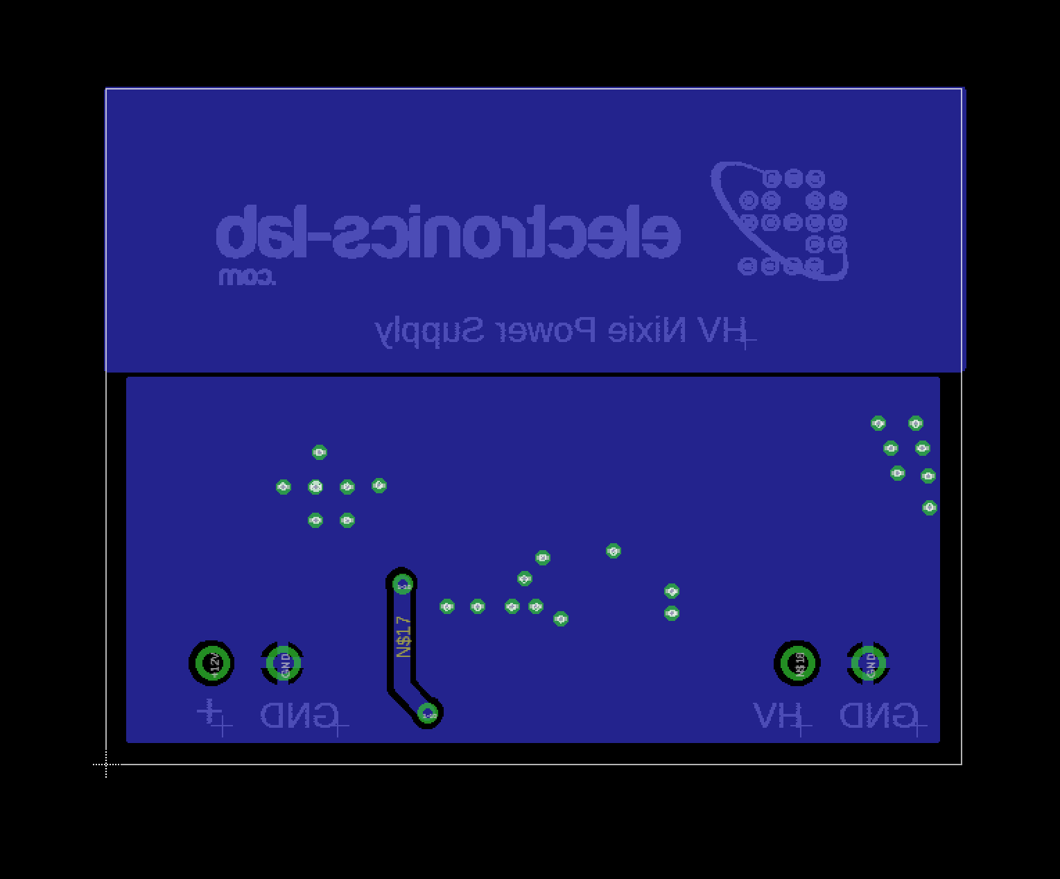
Gerber View
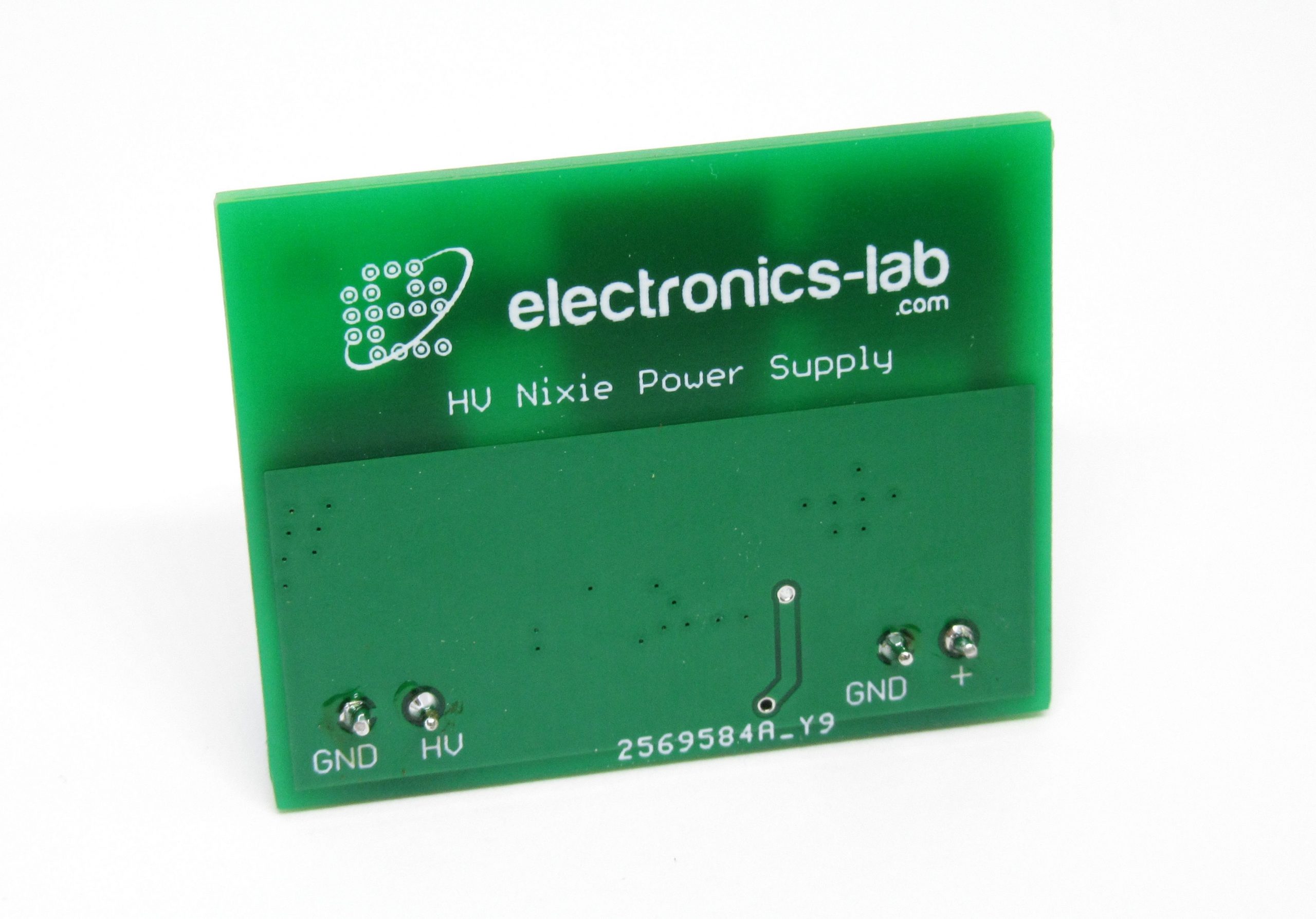
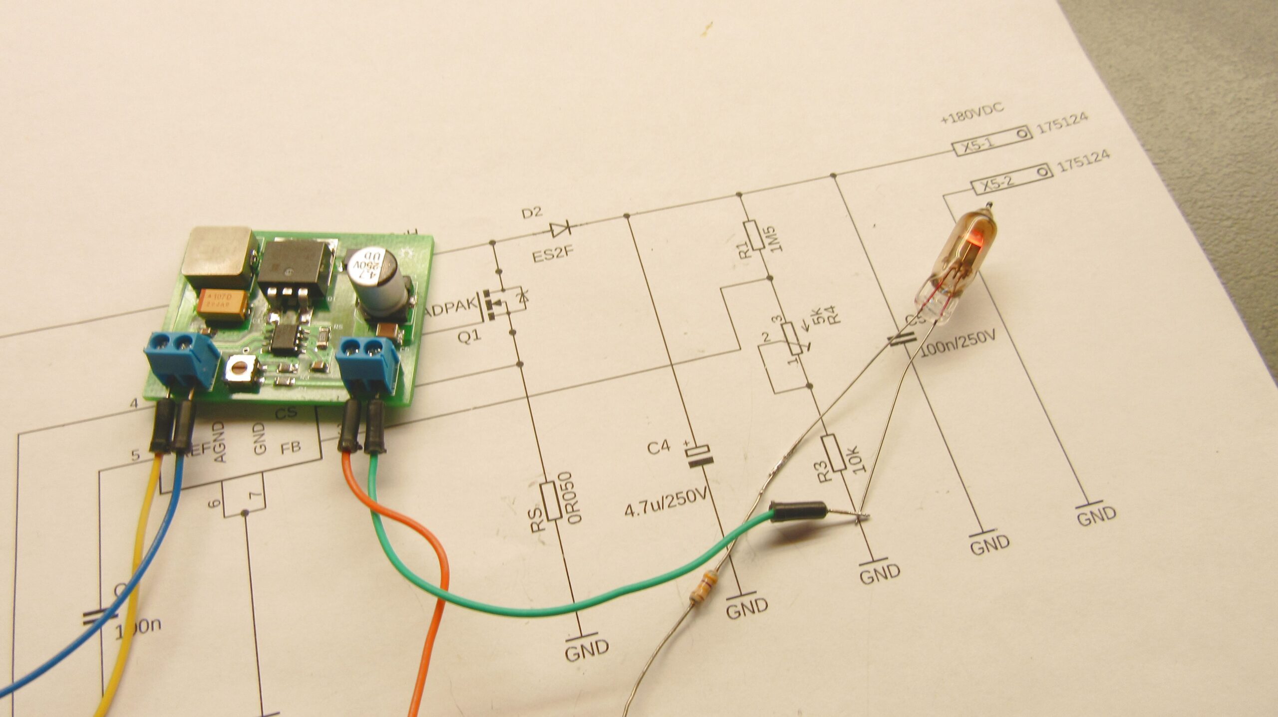
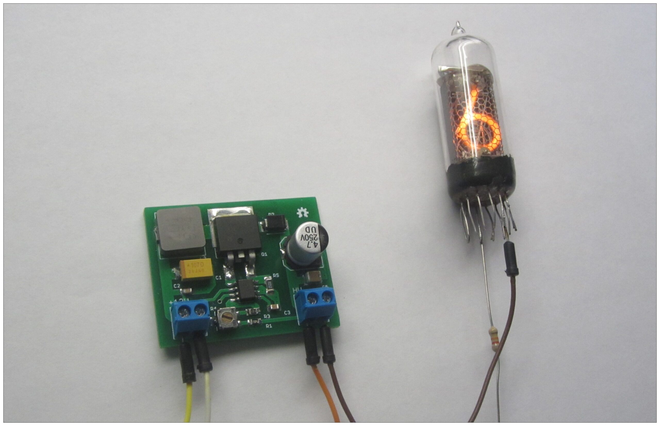
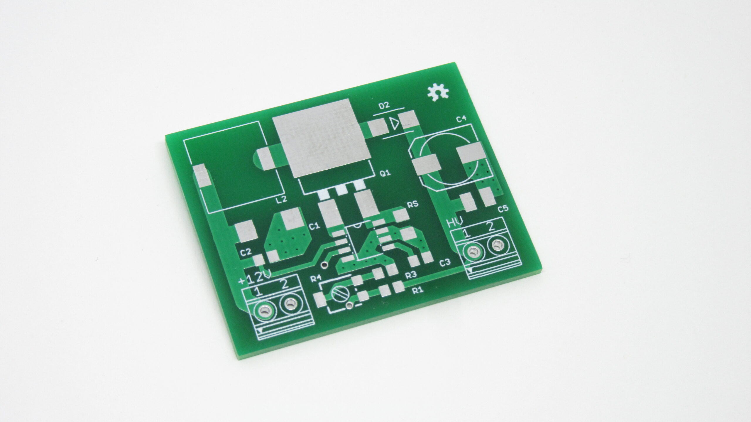
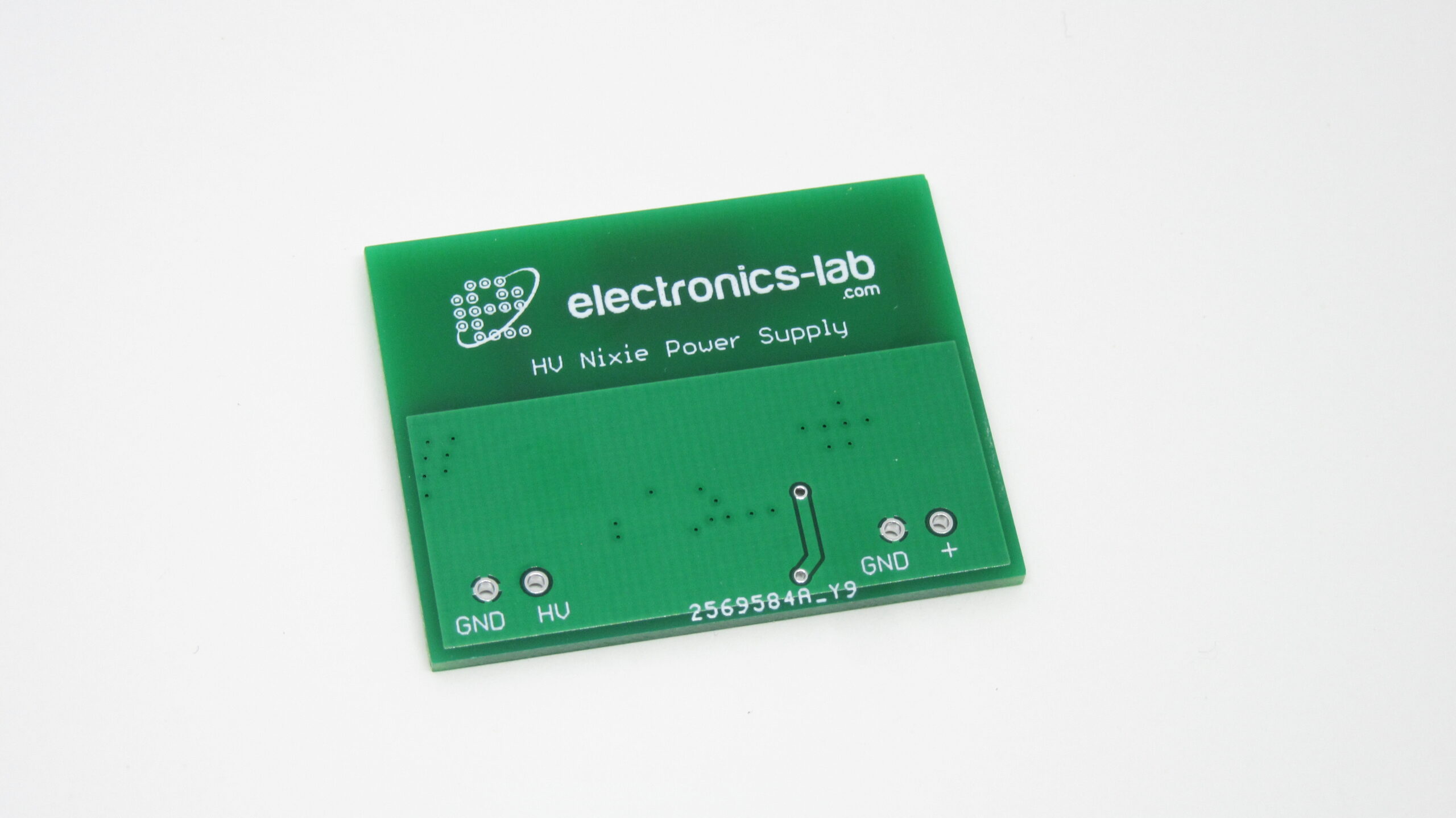
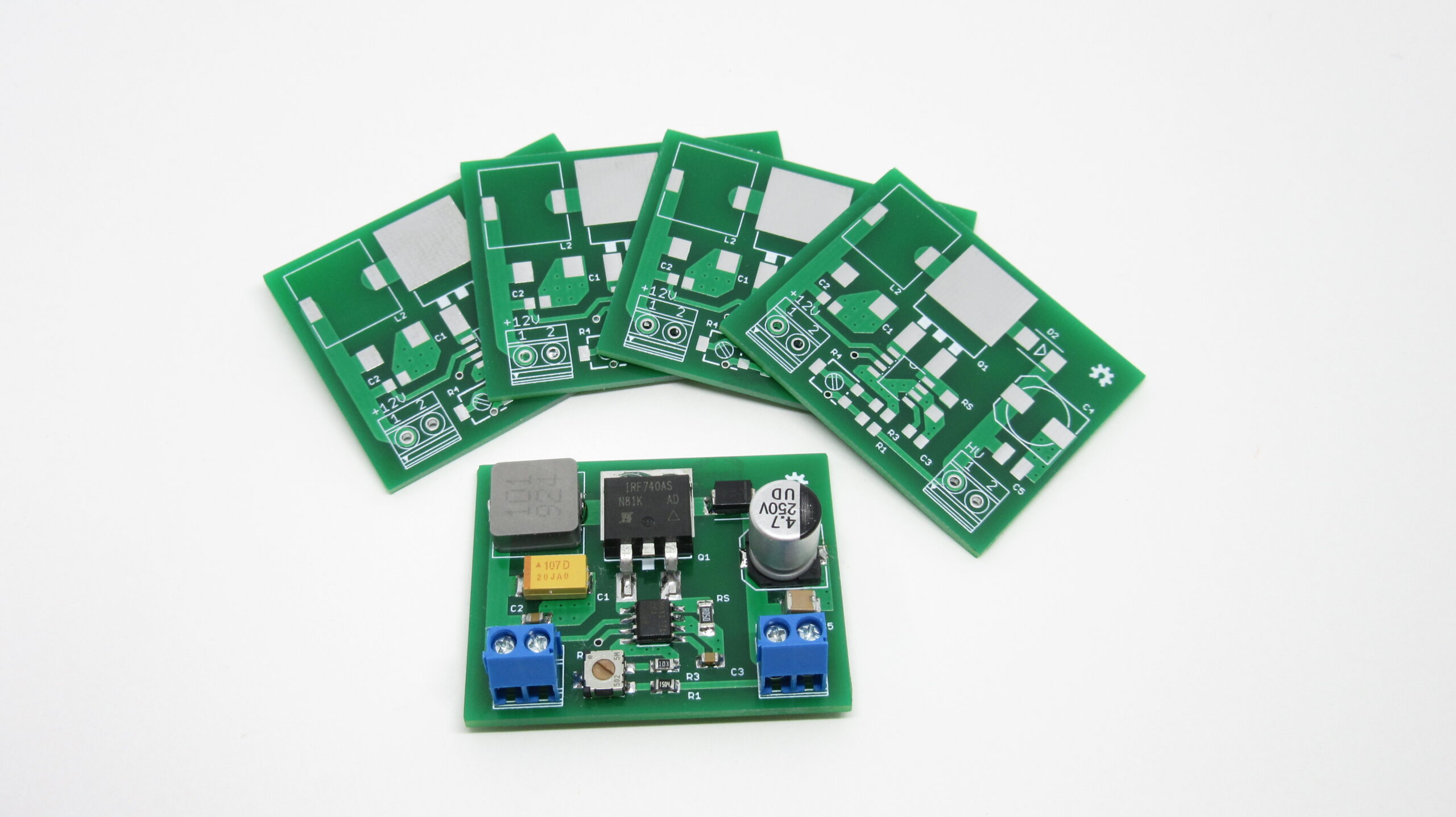
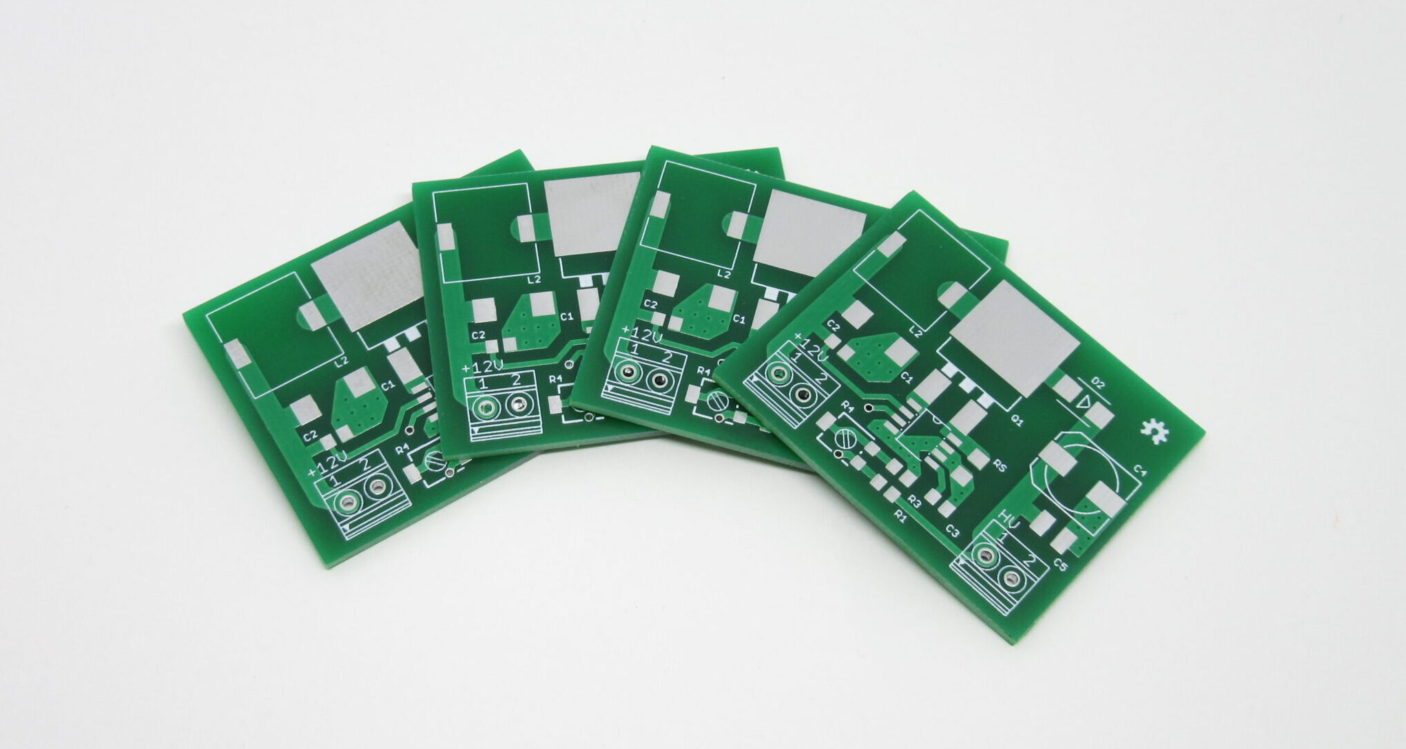
Photos


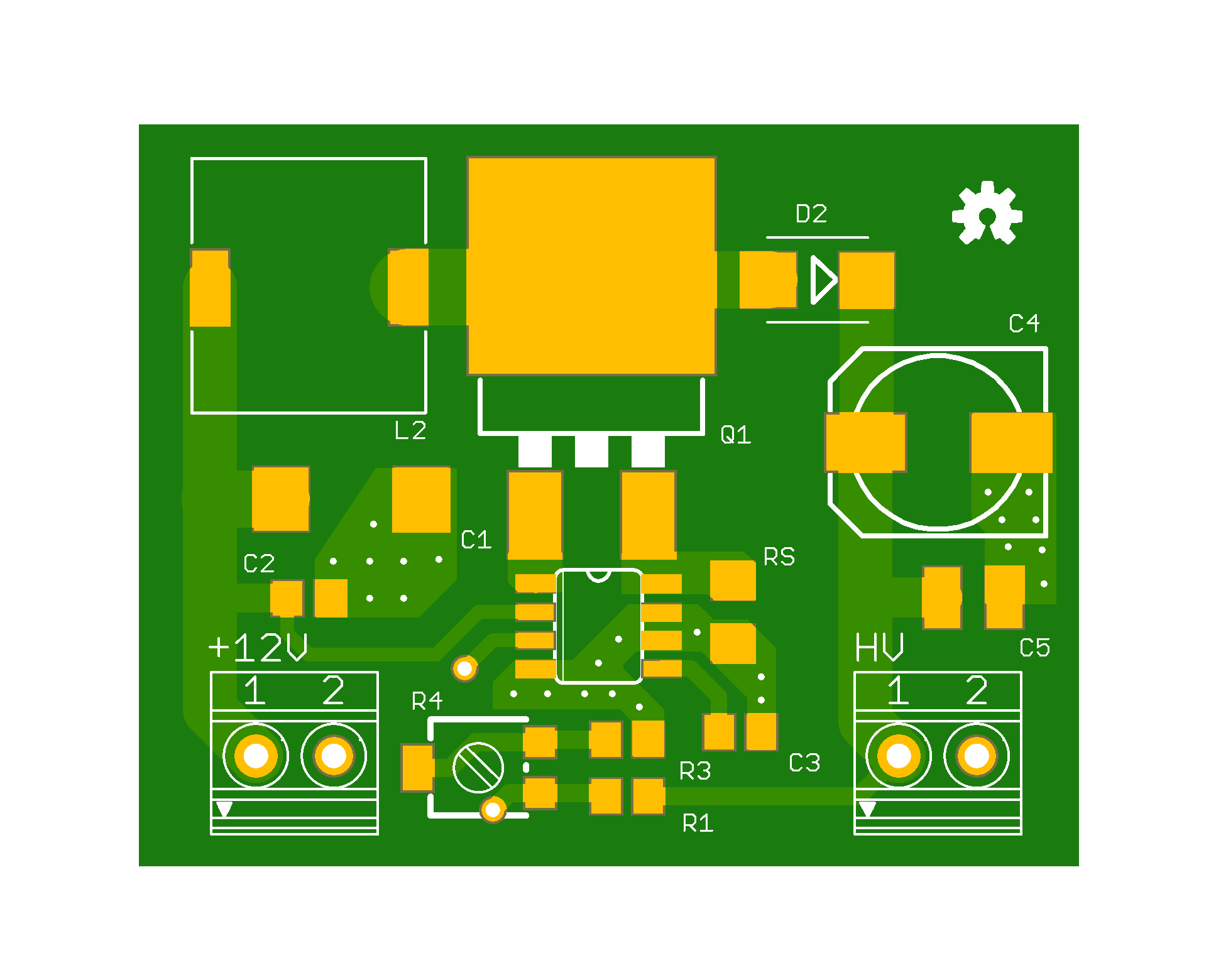


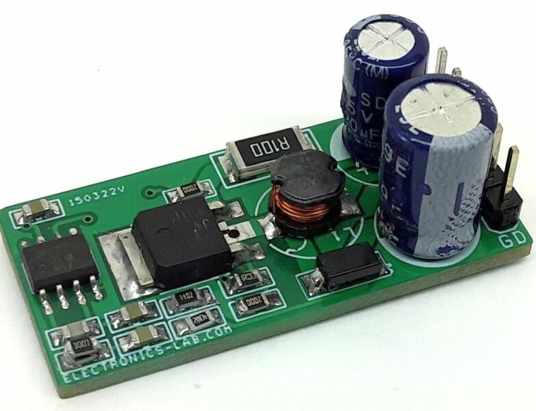
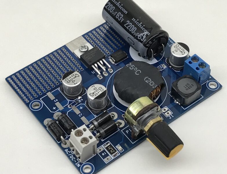
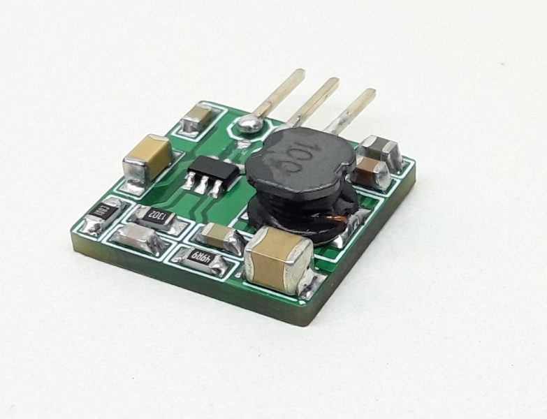
Hi, what is the nominal and or maximal output current @ 180V ?
And you say that i can be powered from 2, to 16.5V. Is it really 2v or 12V ?
Thank you !
It can be powered from 12V to 16.5V. This is fixed in paragraph.
Poor Layout
where is your design ZF
Design is completely updated. Thanks
I think it’s better to have more clearance to GND at the HV Output at the bottom side of your PCB. It seems there is a distance of less 1mm to GND. I would let end of the GND polygon about 1cm before the HV Connector and connect the HV-GND Pin with a single strip to the polygon. It feels a bit safer this way.
Thanks for your input. I agree with you and i will take this into consideration for the next version. If you are familiar with EAGLE, you can do this fix and share with us?
Hello, I am not an expert in mosfets but I wanted to know if I can replace the IRF740ASTRLPBF with IRF740STRLPBF (same reference without the “A”). The datasheet is quite similar and I don’t know if the difference matters for this application…
Yes, you can use it, as the basic characteristics are the same.
Hello!
I would like to use this project, but I can’t open the eagle file. It is corrupt. Can You help me?
Thanks
I’ve updated the zip file with eagle files, could you check again ?
Unfortunetly still wrong. Eagle 7.6 and EasyEDA still can’t open the .brd file.
What error did you get?
In EasyEDA when I try to import the .brd, it says:
“Unexpected error while converting. Perhaps unsupported file type or program bug”
Can You open it in EasyEDA?
You should use Autodesk Eagle to open the files, It seems EasyEDA doesn’t support this file type.
It works! Thanks!
Mike!
Can this power supply do 180V 30-35mA with 12V in?
Sure, it goes up to 50mA @ 180Vdc
And What about heating?
This is a high-efficiency switching regulator and for that input/output, i don’t think it will heat up at all.
Perfect. The PCB already here, i waiting the components. I hope it will be good for me.
Dear Mike! I set up the power supply.On my 6 tube nixie clock the values are this:
In the morning, when 5 tube is in work (0:00 – 9:59) the current is 15-18mA @ 180V
After that (10:00-23:59) when all the 6 tubes are in work the current is 19-22mA @ 180V. The Induction is getting hot. Is this normal, or i make something wrong?
Thanks
How hot does it get? Can you measure it?
~50°C in 30 minutes
I think this is normal for output like that. If you would like to be on the safe side, you may replace the inductor with a bigger one.
Which type / size?
I also get a very hot inductor – any guidance on suitable bigger inductors? (I get a steady 20 ma @ 200V – but it heats up pretty fast and by 30-45 minutes gets hot enough to melt 3D printed ABS parts)
Feel free to try replacing the inductor with a higher power rating, if you would like to use the full output capacity.
Just to say thanks very much for providing this design and the parts list.
I’ve now completed my FLW project that I purchased the tubes for back in 2016.
Two of these circuits on the PCB driving 2 B-7971 tubes each.
Almost 180V right out of the box because the 5K trimmers were supplied centred. Nice!
Hi, I have a module similar to this and I’ve got a question: How would you fix this to the chassis when using the module? This and other similar implementations of HV SMPS commonly don’t have holes for separators. Any Ideas?
Thank you
Yes, right, this is to reduce the overall board size. You can mount it on a chassis using double-sized tape.
Hi, I am curious if I can use a more low voltage, high amperage 3.7v Li-Po to power this. Is there change I have to make with the schematics?
Hi,
How do you increase the output current for this?
(say I want it to give me 80mA)
Hi! Thank you very much for sharing your project.
I was wondering which criteria have you followed in order to choose the inductor inductance and wether it is working in continuous or discontinuous current mode. I also felt curious on how did you decide Rsense value. Maybe using datasheet’s graphics?
Thank you very much once again.
This board is heavily based on this one Nixie HV Switching PSU: https://desmith.net/NMdS/Electronics/NixiePSU.html and the calculations based on datasheet.
Hello,
I would like to know whether the HV Nixie DC-DC switching power supply is RoHS compliant?
Thank you!
Sorry, this is not RoHS compliant.
Awesome. Could be customized to have the SHDN for turning off the power supply/ HV output
How many boards do you need ?
how can adjust the circuit to be powered on 5V? it is more convenient since any smartphone 5V charger could be used
Normally when someone copies a design, they reference the original author prominently in the article and at least ask permission.
This article is almost a direct lift from my own work at https://nick.desmith.net/Electronics/NixiePSU.html – a design that’s been published for more than 15 years and has been used multiple times.