Inductive Proximity Sensor using TCA505
- Rajkumar Sharma
- 15.783 Views
- easy
- Tested
- SKU: EL83195
- Quote Now
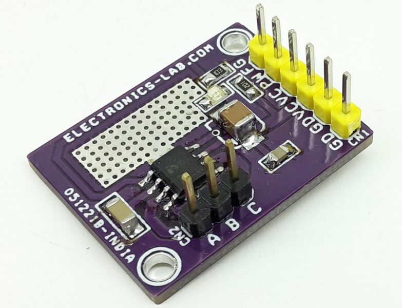
The circuit published here is an Inductive Proximity Sensor, which is used for non-contact detection of metallic objects. The circuit can be used for the detection of metal objects or as a positioning sensor. The TCA505 is used to design an inductive proximity switch that can detect a metal object from 5-10mm range. The resonant circuit of the LC oscillator is implemented with an open half-pot ferrite and a capacitor in parallel (pin LC). If a metallic target is moved closer to the open side of the half-pot ferrite, energy is drawn from the resonant circuit and the amplitude of the oscillation is reduced accordingly. This change in amplitude is transmitted to a threshold switch by means of a demodulator and triggers the outputs. I have tested the circuit with 12V DC however the circuit can also work with higher supply voltage, up to 42V with few components values changes, refer to datasheet for more info. Normally D2 LED is on, when the coil detects the metal object D2-LED goes off and D1 LED turns on, so normally Out-2 provides the low output and Out-1 provides High output when the metal object detected. Q3 Output goes high and Q1 goes Low, both outputs are open collector. PR1 Trimmer potentiometer helps to adjust the sensor sensitivity distance. The output of each transistor can directly drive a small relay as each output has the capacity of handling 50mA of current.
Features
- Supply 12V DC
- Dual Output (Both Open Collector)
- Detection Range 5-10mm
- Dual LED operation
- D2-LED ON Normally Goes OFF When Sensor Detects the Object
- D1-LED OFF Normally Goes ON When Sensor Detects the Object
- PR1 – Sensitivity Adjust
- Both Outputs are Short Circuit Protected
- High Noise Immunity
- PCB Dimensions 30.77mm x 15.54mm
Schematic
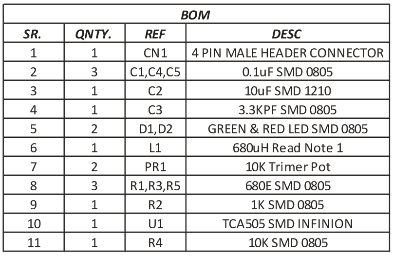
Parts List
Connections


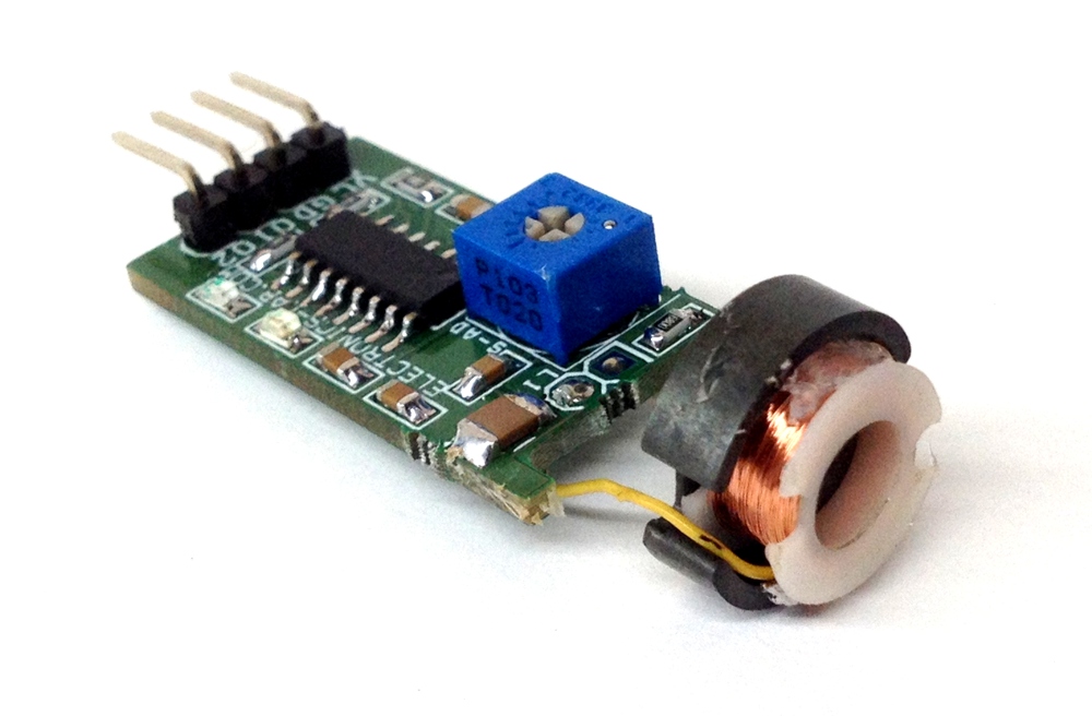



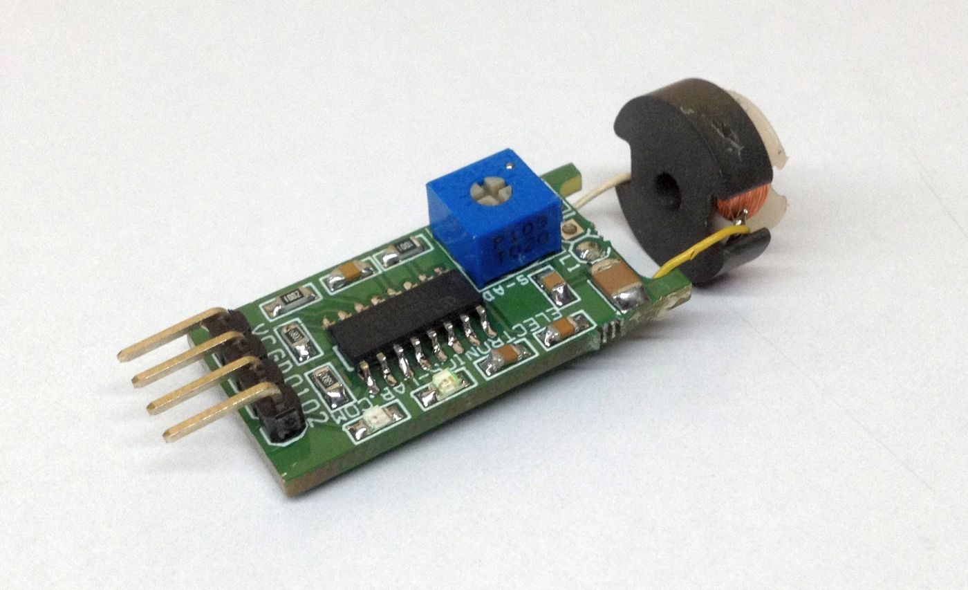
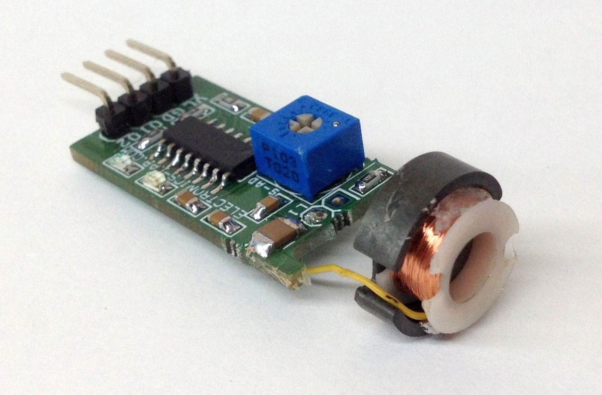
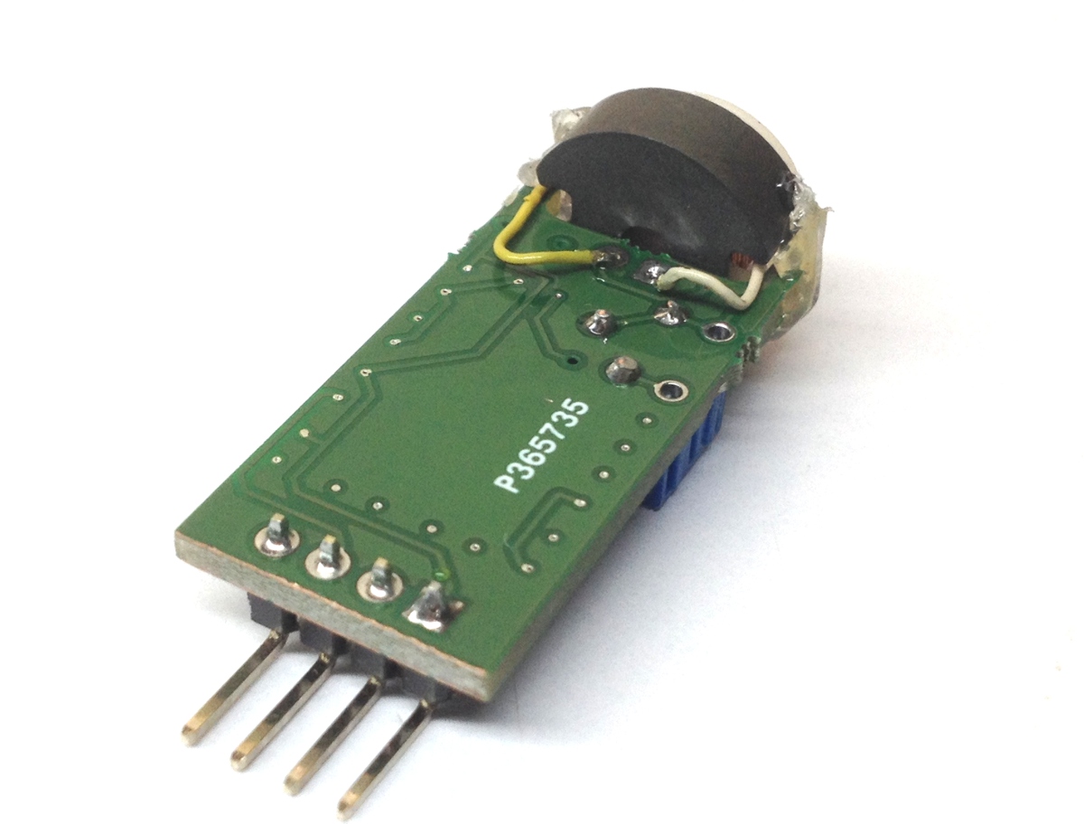
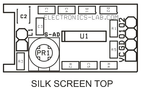
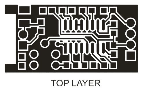
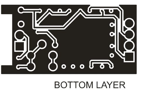


Hi,
I saw INDUCTIVE PROXIMITY SENSOR project in your website. I want to use TCA505 in my project too but I use 24V power supply. Which values and components Should I change? When I looked TCA505 datasheet I couldn’t saw the circuit like your project The datasheet are three types circuit. The circuit in your project doesn’t like these circuits so I wasn’t sure which values to change. Could you help mee to solve this problem?
You can use a voltage regulator to convert 24V to 12V to power this board. Is that you are looking for?
Thank you for your return. But I cant use tca505 because It is not produced anymore so I use tca355 series. But I have problems about LC circuit. I use 400uH pot core(https://www.aliexpress.com/item/1005001613952491.html) and 5,6nf capacitor. But It doesnt work. Also When I read the datasheet tca355 I cant see RDI and RHY values . Could you help me please?
The TCA505 is available from major distributors as it’s indicated above. Have you adjusted the sensitivity trim pot ?