Ingition Coil Driver
- Rajkumar Sharma
- 110 Views
- moderate
- Tested
- SKU: EL155011
- Quote Now
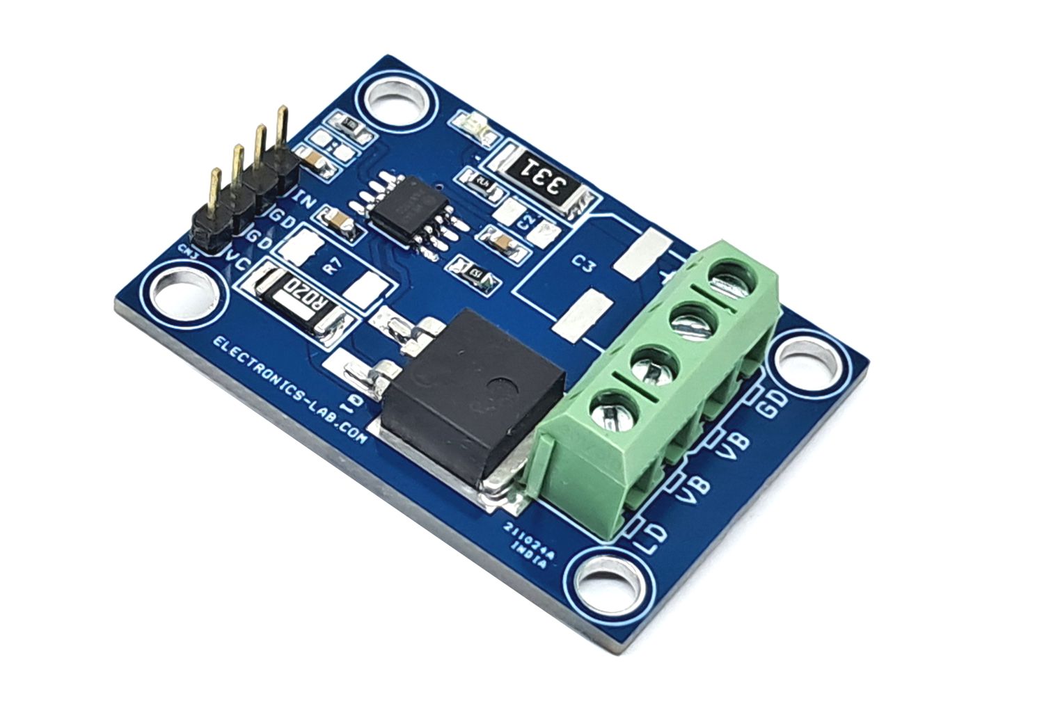
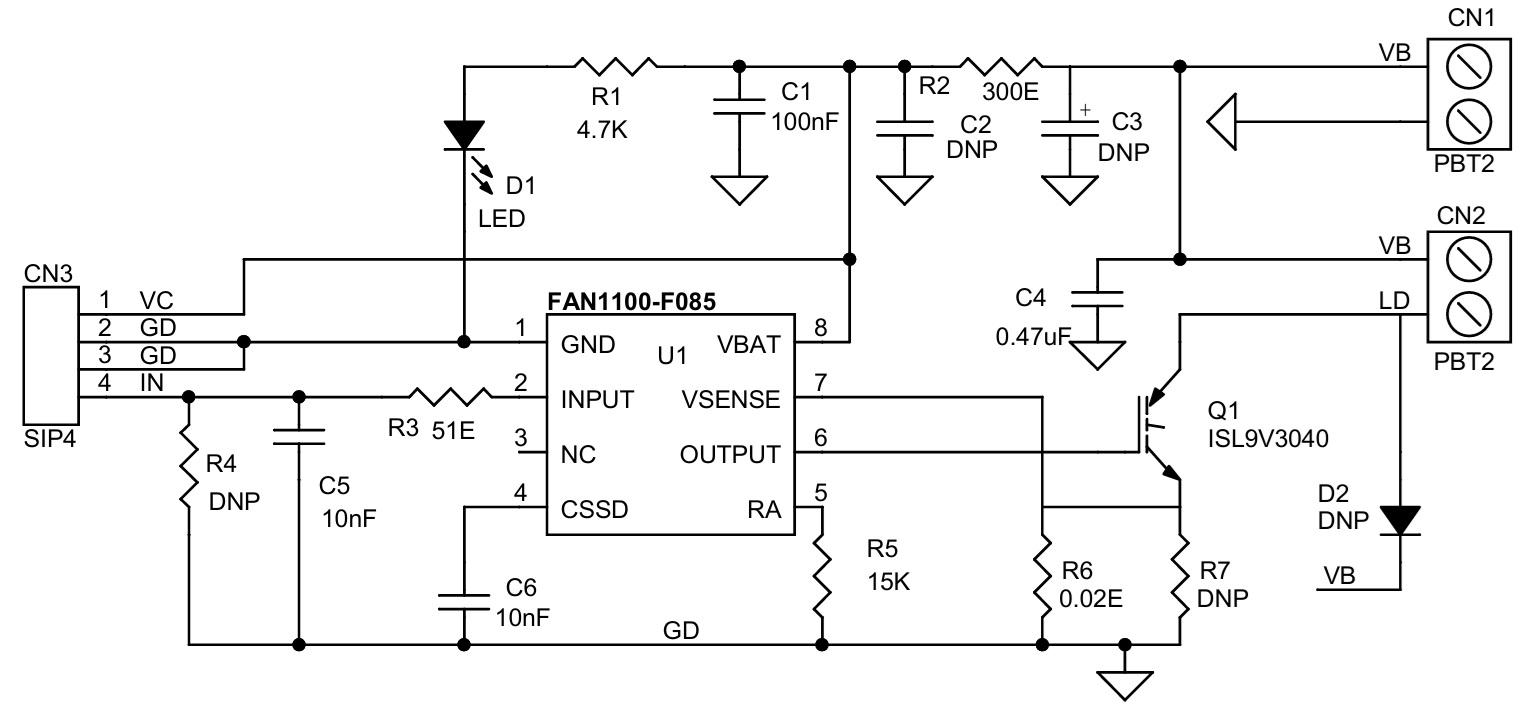
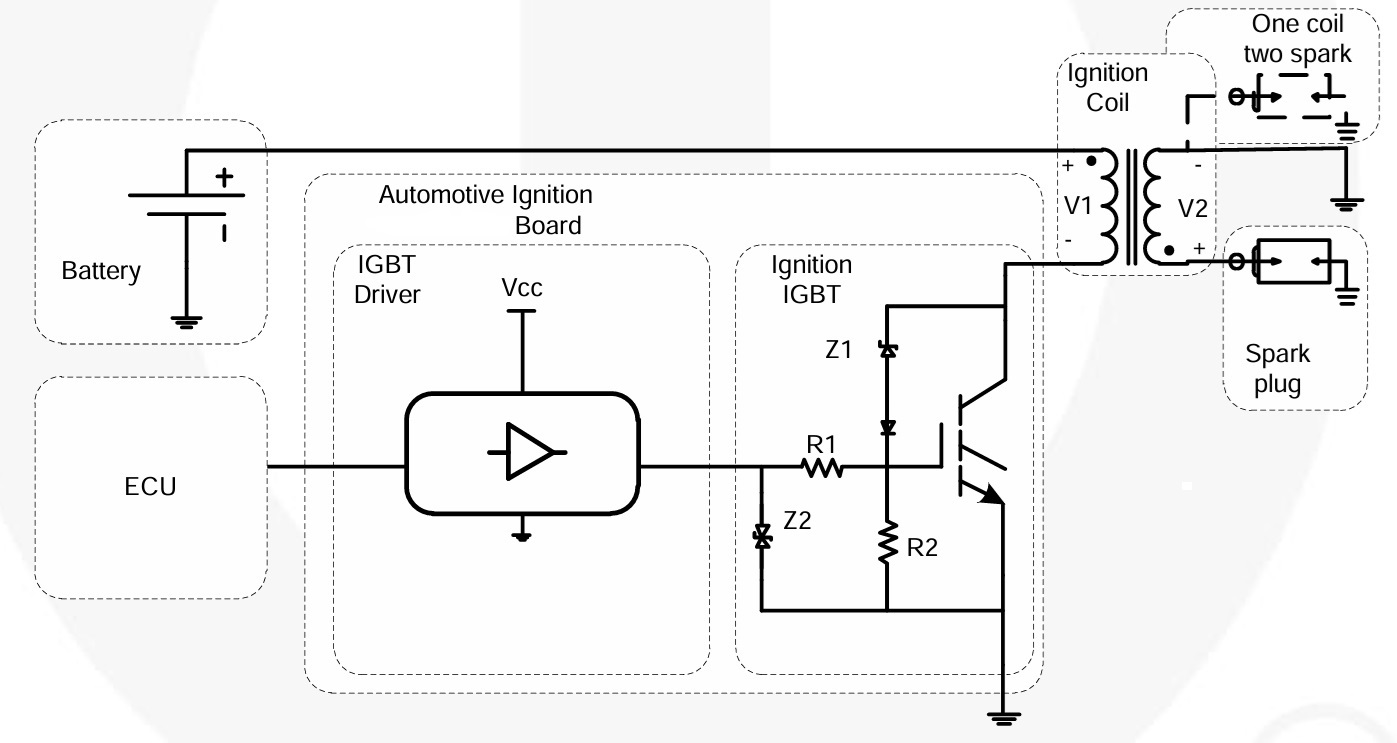
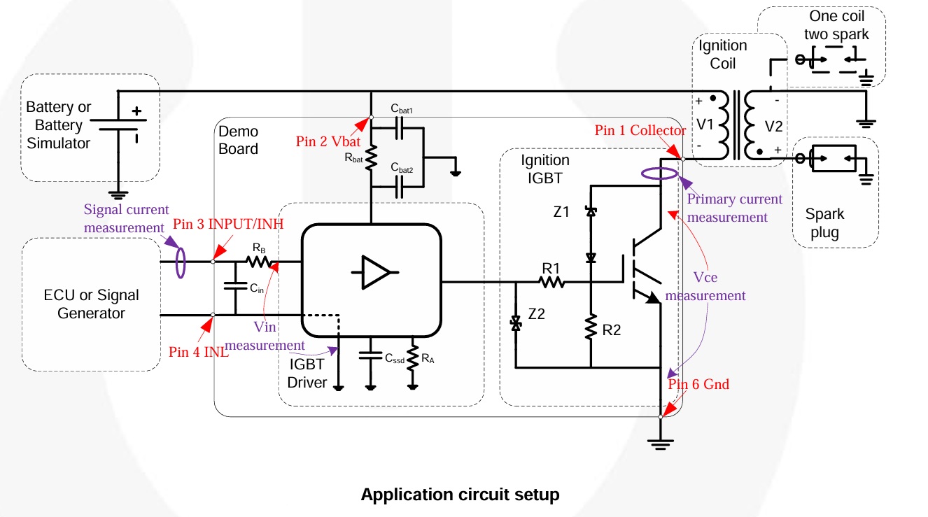
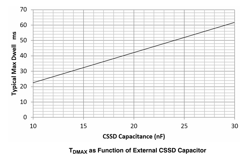
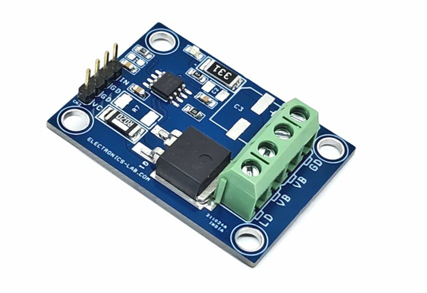
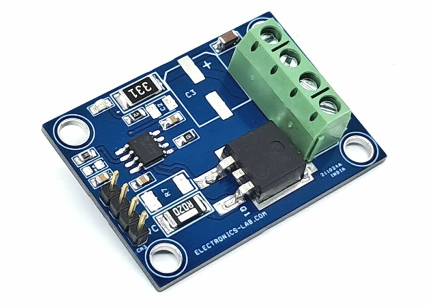
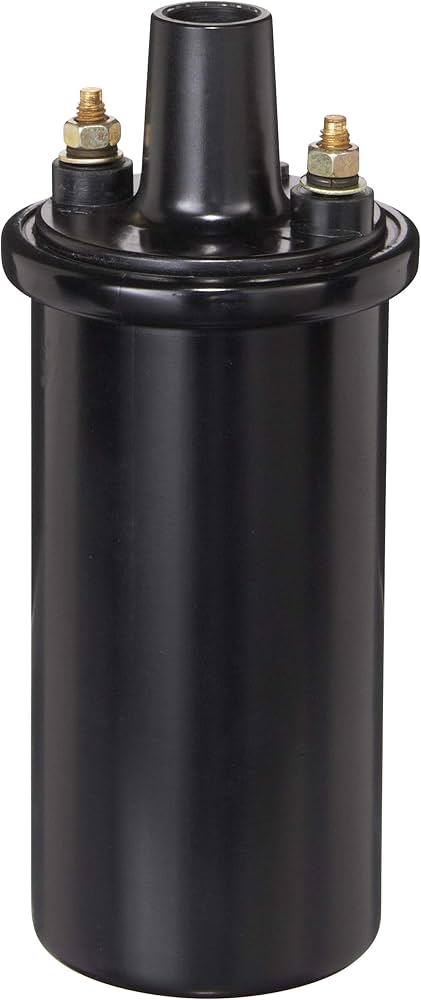
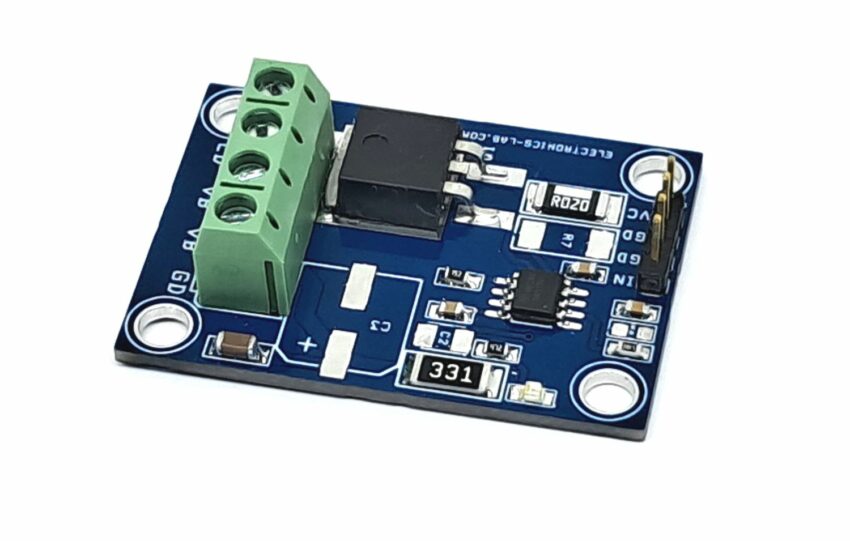
The project presented here is an Ignition coil driver featuring FAN1100-F085 ignition gate driver chip and IGBT. Chip is designed to directly drive an ignition IGBT and control the current and spark event of the coil. The coil current is controlled via the input signal pin. When the input is driven high, the output of the chip is enabled to turn on the IGBT and start charging the coil. Output sink current is programable using resistor R5 (RA). An input spike filter suppresses input signals of less than 13uS in duration. A Max Dwell timer is included in the chip which will turn off the IGBT if input stays active for longer than the programmable time. This time interval can be modified through an external capacitor on the CSSD pin. When the Max Dwell timer is exceeded, the CHIP will enter a Soft-Shut-Down mode (SSD) slowly dropping the collector current by lowering the gate drive to the IGBT thereby discharging the coil such as to inhibit a spark event. Once the soft shutdown operation has started, any transition on the input signal is ignored until after the completion of the soft shutdown function. Chip also limits the collector current of the IGBT during charging. This is done through the sense resistor R6 in the emitter leg of the ignition IGBT developing a signal input to the V-Sense pin of the chip.
Features
- Power Supply 12V to 14V DC
- Input Frequency 5Hz-60Hz (Max 200hz)
- Input Signal 5V Type (Max 6V)
- Signal Line Input Buffer
- Input Spike Filter
- Operation from Ignition or Battery Line
- Ground Shift Tolerance ±1.5 V
- Programmable Maximum Dwell Time
- Programmable Input Pull Down Current
- Control IGBT Current Limiting through VSENSE Pin
- Soft Shutdown following Max Dwell Time Out
- On Board Power LED
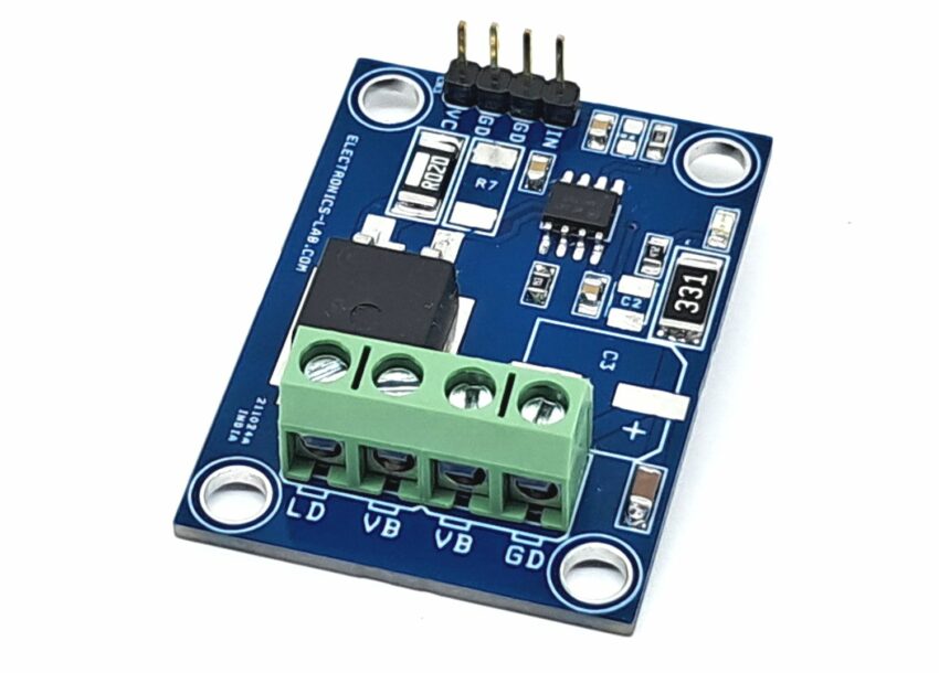
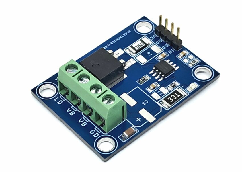
- Screw Terminals for Power Input and Ignition Coil
- Header Connector for Signal Input
- 4 x 4 mm PCB Mounting Holes
- PCB Dimensions 45.09 x 32.39 mm
Recommended Ignition IGBT (Ideal for Coil−on−Plug and Driver−on−Coil Applications)
- ISL9V5045S_F085 450V-500mJ
- ISL9V2040S3S 400V-200mJ
- ISL9V3040S3S 400V-300mJ
- NGB8204N 400V-18Amps
- NGB8206N 350V-20Amps
These Logic Level Insulated Gate Bipolar Transistor (IGBT) features monolithic circuitry integrating ESD and Overvoltage clamped protection for use in inductive coil drivers’ applications. Primary uses include Ignition, Direct Fuel Injection, or wherever high voltage and high current switching is required. Ignition IGBTs are optimized to control the load current through the ignition coil and feature an integrated clamp structure that limits the maximum voltage on the primary side.
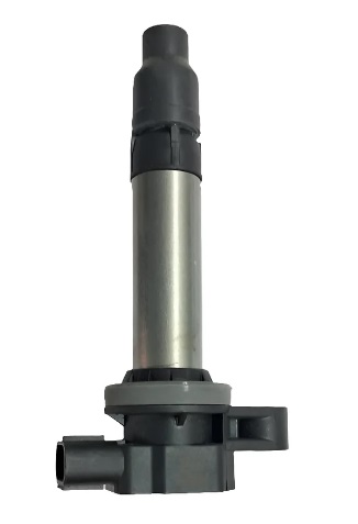
Connections
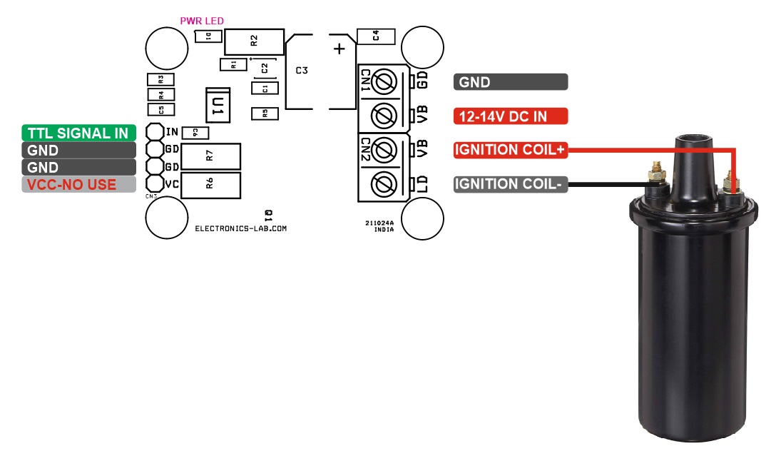
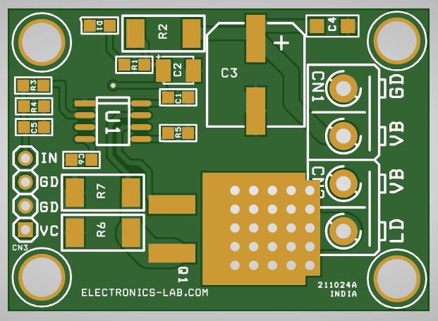
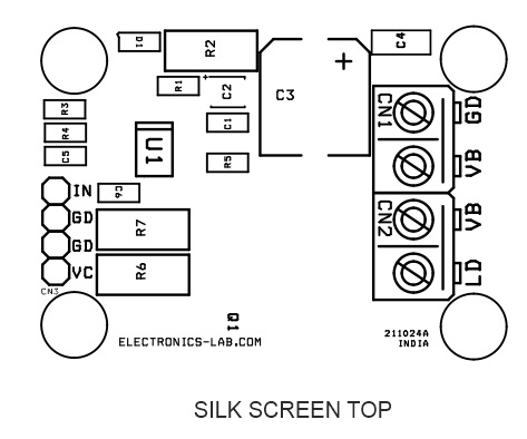
- CN1 Power Input: Pin 1 = Pin 1 +12V to 14V DC, Pin 2 = GND
- CN2 Ignition Coil: Pin 1 = + Coil, Pin 2 = -Coil
- CN3 Signal Input: Pin 1 = VCC No Use, Pin 2 = GND, Pin 3 = GND, Pin 4 = Signal Input (TTL)
- D1: Power LED
Schematic
Parts List
Connections
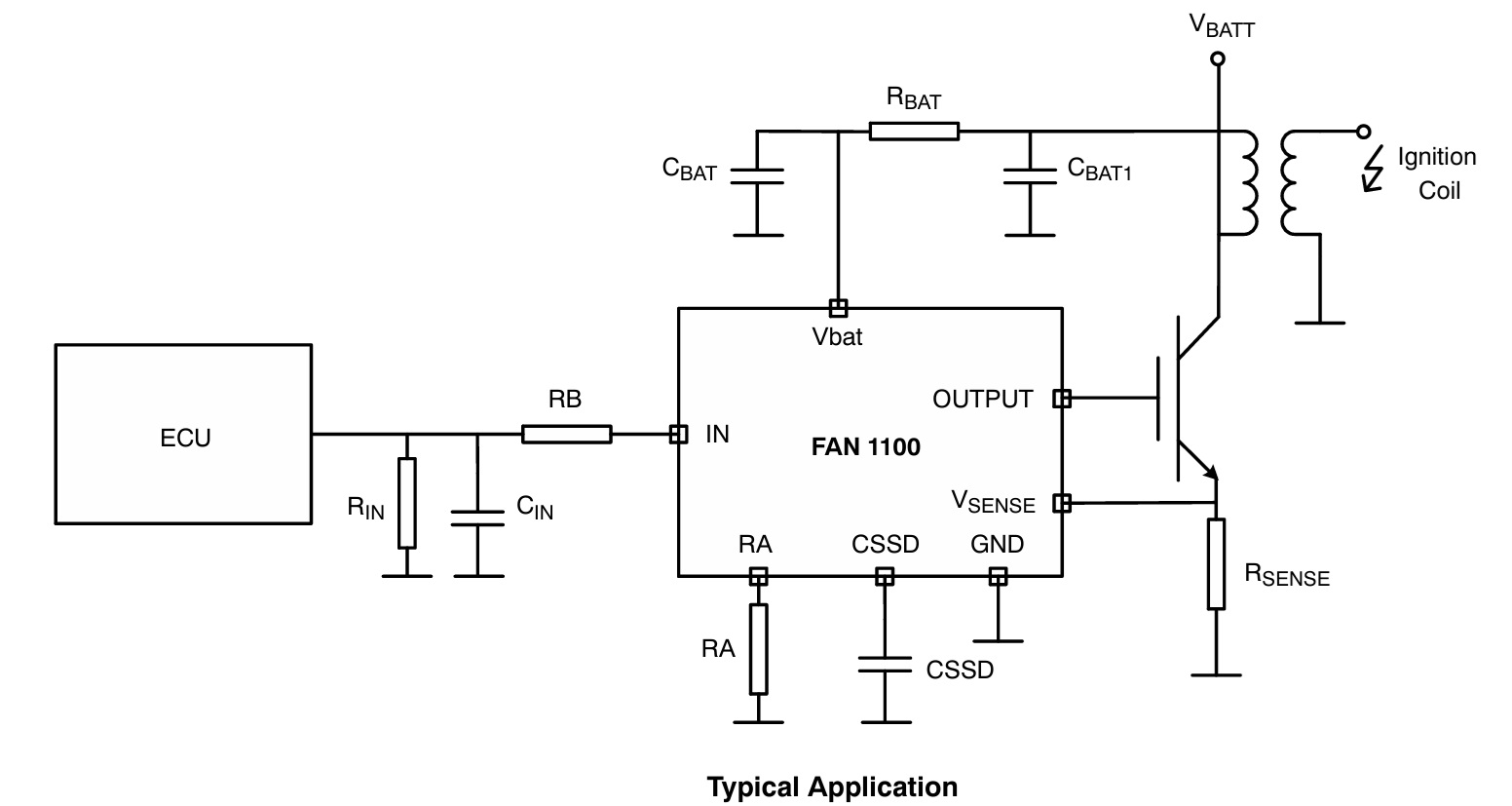
Typical Application
Application Circuit Setup
Block Diagram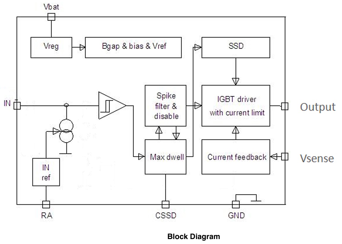
Cssd Capacitor vs Dwell Time
Dwell Time and Soft-Shut-Down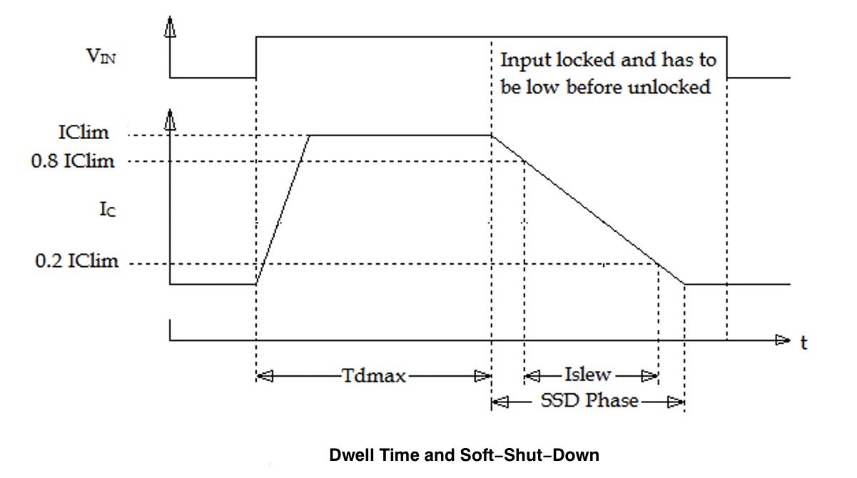
Gerber View
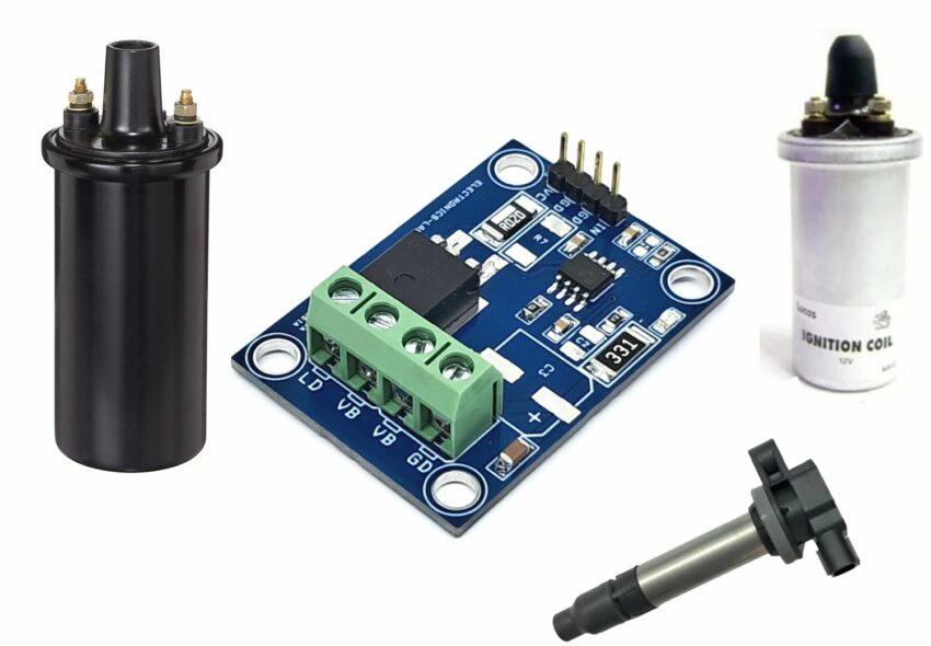
Photos
Video


