Intelligent Power Module (IPM) Board for Brushless Motors
- Rajkumar Sharma
- 20.587 Views
- medium
- Tested
- SKU: EL67293
- Quote Now
Intelligent Power Module (IPM) board has been designed using FSBS5CH60 IC from Fairchild, which provides a fully-featured, high-performance inverter output stage for AC Induction, BLDC, and PMSM motors. These modules integrate optimized gate drive of the built-in IGBTs to minimize EMI and losses, while also providing multiple on-module protection features including under-voltage lockouts, over-current shutdown, and fault reporting. The built-in, high-speed HVIC requires only a single supply voltage and translates the incoming logic-level gate inputs to the high-voltage, high-current drive signals required to properly drive the module’s internal IGBTs. Separate negative IGBT terminals are connected to the shunt resistor to provide the current feedback to the micro-controller. This IPM module helps to develop lots of power applications and also can be used as H-Bridge for brushed DC motor. The module mainly helps to drive Hall sensor-based or encoder-based motors, it doesn’t support the FOC algorithm, FOC-based IPM board is under development and will be published soon.
This board is designed to evaluate Fairchild Semiconductor’s FSBS5CH60. The motion SPM is installed as the motor power module on the board to drive a three-phase AC Induction Motor (ACIM), Brushless DC (BLDC) motor, Brushless AC (BLAC) motor, or Permanent-Magnet Synchronous Motor (PMSM). The board has bulk capacitors and microcontroller (MCU) interface circuitry. As this board is designed for a wide variety of motor types, not all included circuitry is required for all types of motors. Some motor types may require some additional circuitry be added, depending on the control algorithms being implemented.
The board is designed to connect DC power sources feeding current to the motor. The three-phase motor output terminals (U-M1, V-M2, W-M3) from the screw terminal should be connected to the motor windings. Three bootstrap power supply circuits are designed into the board, one per phase. A bootstrap capacitor, charge resistor for charging the capacitor, and the blocking diode for high-voltage isolation make up each bootstrap supply. The microcontroller (MCU) or motion-controller development board connects to this IPM board via the provided 16 Pin header connector. Six low-pass filters are used between the signal input connector and the gate input signal pins of the IC. Short-circuit current protection is provided by a single shunt resistor, op-amp, and low-pass filter. Additional resistor divider circuitry is included to monitor bus voltage, inverter phase current, and module temperature.
This board is made for low voltage motor up to 90V DC load up to 5Amps, however it can be used for higher voltage motor up to 400V DC by changing bulk capacitor, refer note for more details. Two 4mm holes were provided to mount the heat sink on top of the IC. The board also works with 28-40 Pin PIC Micro-Controller and dsPIC shield which helps easy interface with many PIC micro-controllers and Motor dsPICs. 16 PIN header connector can be hooked up to any port pin of PIC/dsPIC development board using female to the female wire harness.
Safety precautions Warning
Notes
- Note 1: This board support Motor supply up to 90V DC ( High Supply Input possible refer Note 2)
- Note 2: For higher supply input Change bulk capacitor C6, C7 voltages as per higher supply requirement, extra safety precaution needed to handle the board for higher dc voltage supply input.
- Note 3: PR1 Trimmer potentiometer provided to set the over current output, over current detector circuitry is built using comparator.
- Note 4: Refer data sheet of FSBS5CH60 IC for more information about input signals and rest features.
- Note 5: For bus voltage feed, Choose R5, R6 Resistors as per application requirement.
Features
- Supply Up To 90V DC 5Amps
- Load 90V DC Up to 5Amps
- Logic Supply 5V DC ( For Op-Amps)
- Gate Driver Supply 15V DC
- Current Feedback Output 200mV/1Amp
- Fault Output Normally High, Goes low at Over Current set point
- Trimmer Potentiometer PR1 to set the over current output
Inputs/Outputs 16 Pin Header Connector
- Pin 1 5V DC In for Op-amp and Comparator
- Pin 2 GND (Ground)
- Pin 3 M1 Low-In (U)
- Pin 4 M1 High-In (U)
- Pin 5 M2 Low-In (V)
- Pin 6 M2 High-In (V)
- Pin 7 M3 Low-in (W)
- Pin 8 M3 High-In (W)
- Pin 9 Bus Voltage Feedback Output to Micro-controller
- Pin 10 CSI Current Sense Voltage Output 200mV/1amp
- Pin 11 over Current/Fault Output To Micro-Controller Normally High Goes Low at Over Current (Comparator)
- Pin 12 Short Circuit Current Detection
- Pin 13 Fault Out IPM IC
- Pin 14 Not In Use
- PIN 15 GND
- Pin 16 15V DC Supply Input for Gate Drivers
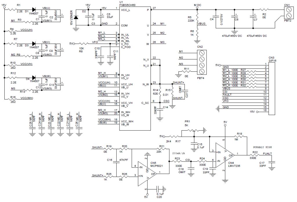
Schematic
Parts List
| SR. | QNTY | REF | DESC |
|---|---|---|---|
| 1 | 1 | CN1 | 2 PIN SCREW TERMINAL |
| 2 | 1 | CN2 | 4 PIN SCREW TERMINAL |
| 3 | 1 | CN3 | 16 PIN HEADER CONNECTOR |
| 4 | 1 | CN4 | LMV7235 SMD |
| 5 | 1 | CN5 | MCP6021 SMD |
| 6 | 6 | C1,C3,C8,C12,C15,C20 | 0.1uF SMD 0805 |
| 7 | 3 | C2,C9,C13 | 33uF35V |
| 8 | 1 | C4 | 0.1uF/630V |
| 9 | 1 | C5 | 33uF/35V |
| 10 | 2 | C6,C7 | 470uF/100V |
| 11 | 2 | C10,C14 | 33KPF SMD 0805 |
| 12 | 1 | C11 | 1KPF/50V SMD 0805 |
| 13 | 1 | C16 | 47KPF SMD 0805 |
| 14 | 2 | C17,C19 | 33PF SMD 0805 |
| 15 | 2 | C18,C27 | OMIT |
| 16 | 6 | C21,C22,C23,C24,C25,C26 | 1KPF SMD 0805 |
| 17 | 3 | D1,D3,D4 | 1N4007 SMD 4007 |
| 18 | 1 | D2 | 15V/1W ZENER |
| 19 | 1 | PR1 | 5K TRIMMER POTENTIOMETER |
| 20 | 7 | R1,R3,R4,R7,R9,R12,R13 | 2.2E SMD 0805 |
| 21 | 4 | R2,R11,R19,R26 | 0E SMD 0805 |
| 22 | 1 | R5 | 220K SMD 0805 |
| 23 | 3 | R6,R20,R25 | 1K SMD 0805 |
| 24 | 1 | R8 | 10K SMD 0805 |
| 25 | 2 | R10,R16 | 2.2E SMD 0805 |
| 26 | 1 | R14 | 62E SMD 0805 |
| 27 | 1 | R15 | 0.01/3W |
| 28 | 1 | R17 | 2K4 SMD 0805 |
| 29 | 1 | R18 | 1M SMD 0805 |
| 30 | 1 | R21 | 20K SMD 0805 |
| 31 | 3 | R22,R23,R24 | 330E SMD 0805 |
| 32 | 6 | R27,R28,R29,R30,R31,R32 | 100E SMD 0805 |
| 33 | 1 | U1 | FSBS5CH60 FAIRCHILD |
Photos


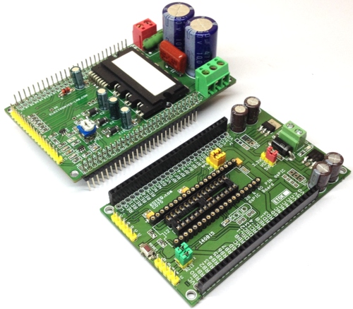
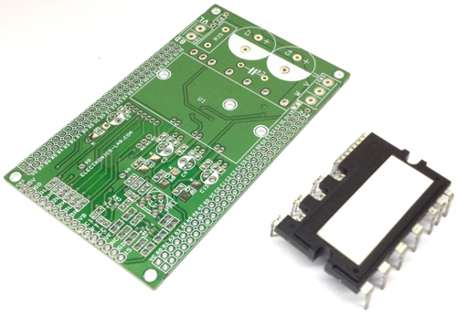
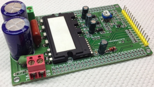
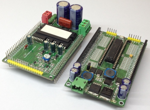


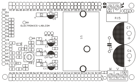
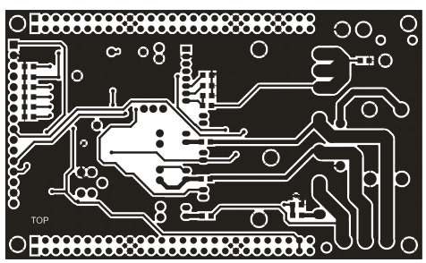
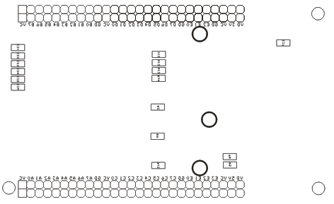
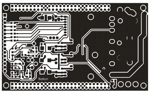


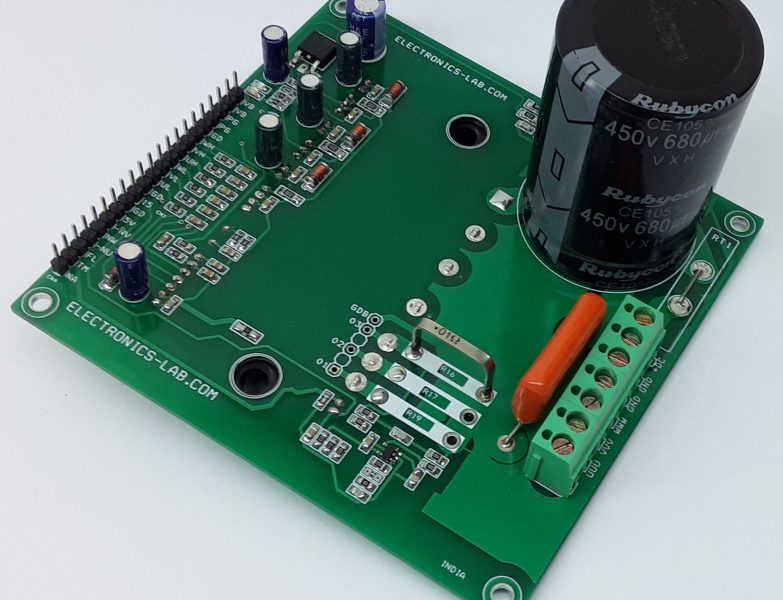
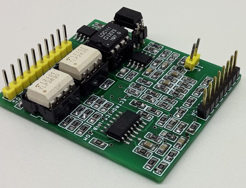
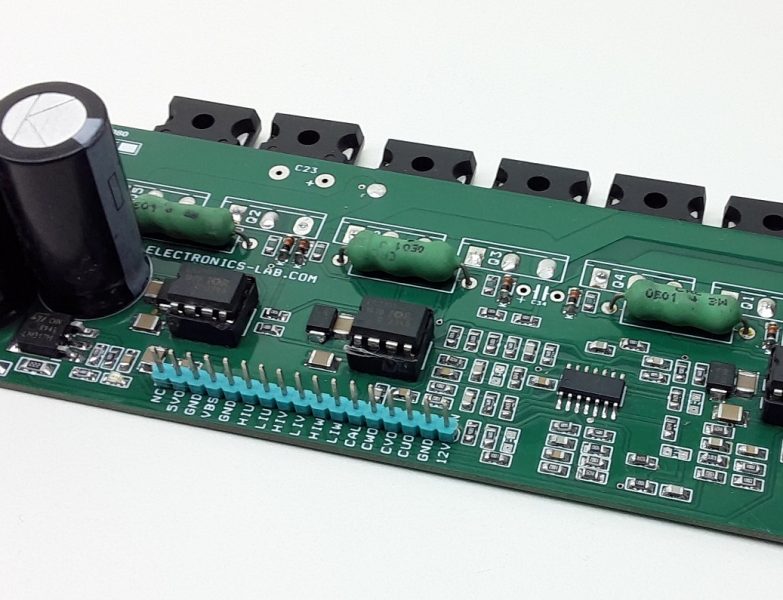
How can i buy these shields??
How many pieces do you need?
How to buy ipm board for brush less dc motor
How many pieces do you need?
IRMCK343 imotion control ic is most probably use with IPM Modules. I have seen soo many circuit using that. Could you able to explain how it is useful and how to integrate it if it is helpful. IRMCK343 is a infineon make.
how much pre unit
Hi am new to this stuff but I have some motors and and inverted board I salvaged from a panasonic real pro elite ep3222 massage chair. From what I could find is that the board has 3 either Mitsubishi or powerex super mini dipipm’s on it for motor control the motors are also a mystery could not find any info on them but since the board has those ipms it should be one if a few types probably bkdcbldc or pmsm. Anyway I wanted to see if I could modify your boards to fit those ipms or just use yours to control them.
Warning! C9 direction is wrong.
in bottom copper, the line from shunt upper arm had been short circuited to pin 13 Vcc of FSBS5CH60, so +15V is shorted to gnd.
Could you point this to a drawing? I can’t figure our what you are talking about.
Hi. I’ve just built one similar to this, using MC3PHAC and the FSBS10CH60 circuit.
Just thought I’d ask if anyone here have had similar problem getting the thing working:
I’ve go no signs of life, clock I think is working, but I’ve got the funniest measured value of the FOR/REV pin (With pull-up to 5V) of less than 10 mV not shorted. The other pins shows above 4V, and the Fault-pin is a constant low…
A small update.
I’ve determined that the MC3PHAC circuit is faulty. I’ve got a constant voltage between For/Rev pin of about 5 mV, like before. I even tested putting an LED with resistor over it and there’s enough current to drive it. Putting only a resistor there makes it hot, so something is definitely wrong with it, so I’m looking to replace it.
Anyone had this problem before?
Seem odd that it would happen to a relatively new circuit.
Guessing it’s been shelved for a number of years, and maybe the seller on Ali Express was careless in the way of how it was stored. It came in a reel cut-out strip, in an ordinary Zip-bag, which might have affected it, I don’t know.
Could have been from a botched batch from the manufacturer too.
Hi,
Maybe someone has the ”40 PIN & 28 PIN DSPIC DEVELOPMENT BOARD” GERBER files it would really help with the school project.
Could you send me them to my email: benasqaz@gmail.com
Thank you very much.
Gerber files are under downloads on this page.
Another update.
Ordered a new circuit, and it starting to look like that the clock isn’t working, or at least that’s what I can come up with.
Have the same problem after installing the new IC, which is of another brand even. Still the same result. Forward/Reverse pin is drawn low, leaving a few mV towars ground.
The schematic I used suggests that I use 22 pF capacitors, but the datasheet for the crystal suggests 30pF, so I’m thinking of ordering new ones and see if that does the trick.
I should mention that I don’t have an oscilloscope so I can’t verify whether or not it’s working, and I was thinking of perhaps using an Arduino to check frequencies, but I’m quite reluctant since there’s high voltage on the board and the fact that measuring the oscillator pins might give false readings due to resistance on the Arduinos input might interfere with the crystal.
Still, I find it funny that this particular pin which has no other purpose than being an input is showing this behavior.
But, two circuits showing the same thing must mean that there’s something else going on, and my present conclusion is that it’s the clock that’s not working, causing some (weird) function so that pin goes low…
Oh, well. I’ll order new caps and try, then I’ll post the update, again…
And another update.
Turns out I had some minor not so major problems!
First I replaced the caps, which didn’t work, so I also replaced the crystal. Still no change.
Then, for a brief second when I was randomly pushing buttons (I have three on my board for start,reverse and reset), the corner of my eye caught a movement. As I lifted my head towards the washing machine I accidentally slipped my finger from the button, but at least I saw it rotating. Tried pushing it again – Nothing.
So, tried adjusting the DC-bus while measuring it so that I’d have the correct voltage of around 4,7 v, and also checked the speed-pot’s voltage, and found that I had only a few mVolts. I then checked the board (I have an IDC connector to which I’ve attached leads to the pot) I saw that it had been connected to the wrong pin.
So, apparently I had just enough voltage for it to move (It turned incredibly slowly, a slight miracle that I even noticed it in the first place!), but as soon as I let the button go it changed to another value or something..
Anyways, connected the right pin, and suddenly it was running and I could adjust the speed.
But, I still had the problem that the Forward/Reverse pin was essentially shorted, and seeing as how I had problems around the IDC connector, I took a look beneath the board and found that one of the leads had been shorted to 5V.
This lead goes to one of four Opto-couplers of which three of their “backsides” goes in parallel with the on-board switches,
Suddenly I undestood why I had a short on that pin while it was powered, and measured at high Ohm when power was off.
Scraped with an scalpel, replaced one of the opto-couplers (Was not working, burned for some reason to me unknown), and it effin’ worked!
I can now run it in any direction!
I had ordered and waited around almost 3 full weeks for new components, that I really didn’t need.
It also turns out that just by putting the probes between DC-bus->Pot (Which is a potential to measure voltage drop due to high load and/or faliures) the voltage dropped enough to generate a fault-signal to the driver circuit, causing the MC3PHAC not to work.
So, no wonder I had no luck getting it going.
I noticed it when I tried adjusting it and it suddenly stopped running, and I thought I’d broken something. During this I had my probe on it!
But, when I removed the probe it started up as it should, and as soon as I put the probe back on it stopped, abruptly and had to be reset (By the RESET-input) in order to start again.
So, if anyone else is having this problem, this might be helpful.
As for the functionality of the circuits (MC3PHAC and FSBS10CH60) – I really love how smooth it runs. Either it’s super soft start taking multiple seconds from start to full RPM, or it’s really quick respons and even brakes (Without a resistive circuit) very quickly.
This driver would fit almost any application.
I’m sure there are newer replacements, because MC3PHAC is hard to come by nowadays, but Ali Express or eBay still lists a few sellers. It’s expensive as hell though, but definitely worth every dime/yen/pesetas/Crowns or whatever currency you’d prefer!
Hi,
I could not find the resistors R10 R16 2.00E+02 could someone specify what type are they and a link would be very nice.
Thank you.
R4, R10, R16 all are 2.2 Ohms resistors just for overcurrent protection to VCC Pins of each gate driver, they also can be replaced with 0 Ohms
las dos tierra del pin COM y el pin N del integrado tienen que ir separadas, eso lo dice la nota AN9035 de On semiconductor que trata de los integrados FSBxxCH60.
The two ground of the COM pin and the N pin of the integrated have to be separated, that says the note AN9035 of On semiconductor that deals with the FSBxxCH60 integrated.
we want to buy this module ..?
What is OMIT Capacitor please tell
OMIT means do not place.
What is 2.00E+02 in part no 25 ie.R10, R16 Please tell.
It’s 2.2Ω SMD 0805, fixed on the BOM List
can you please suggest a replacement for LMV7235 and MCP6021..?