Interactive LED Coffee Table – Arduino Compatible
- Rajkumar Sharma
- 493 Views
- easy
- Tested
- SKU: EL130660
- Quote Now
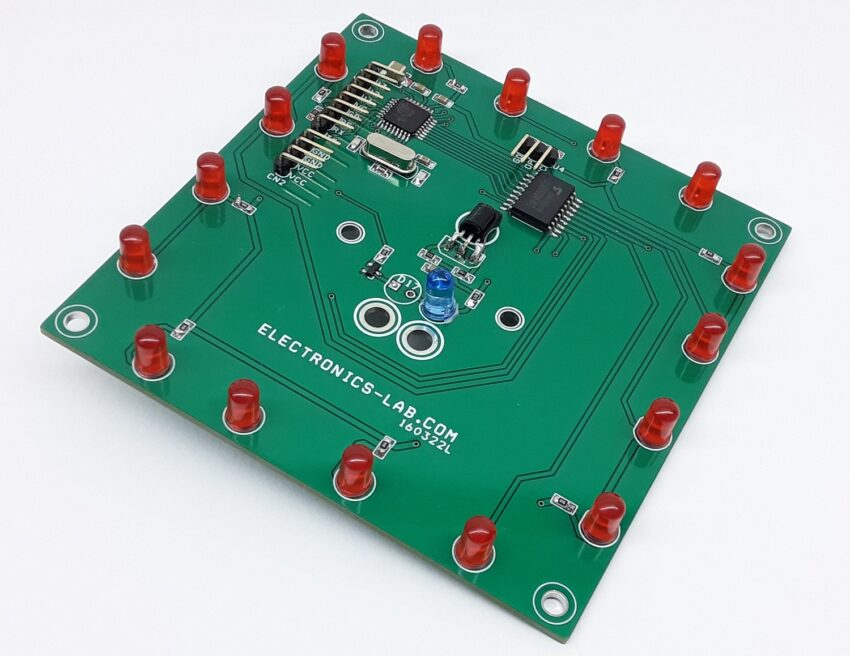
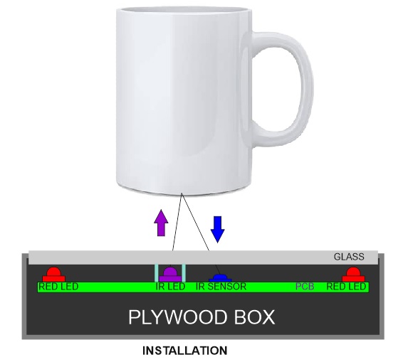
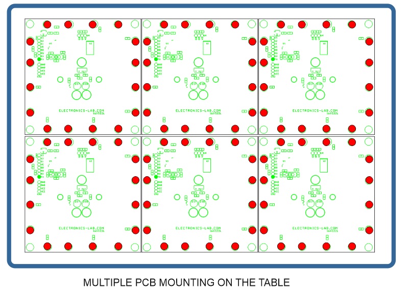
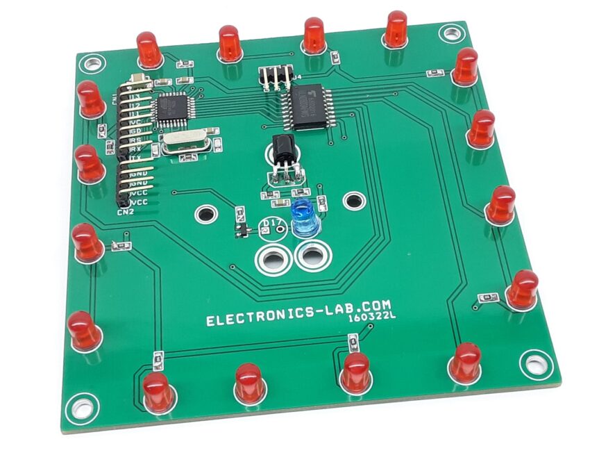
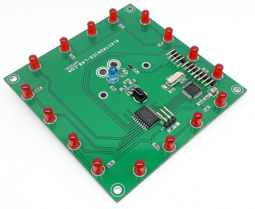
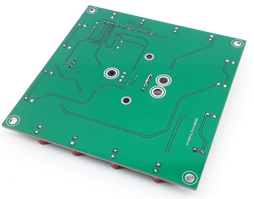
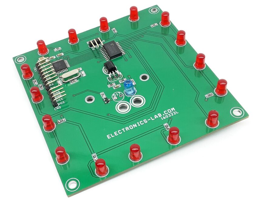
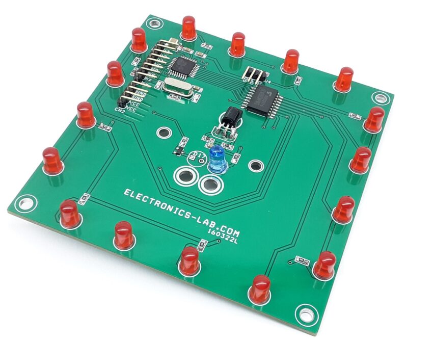
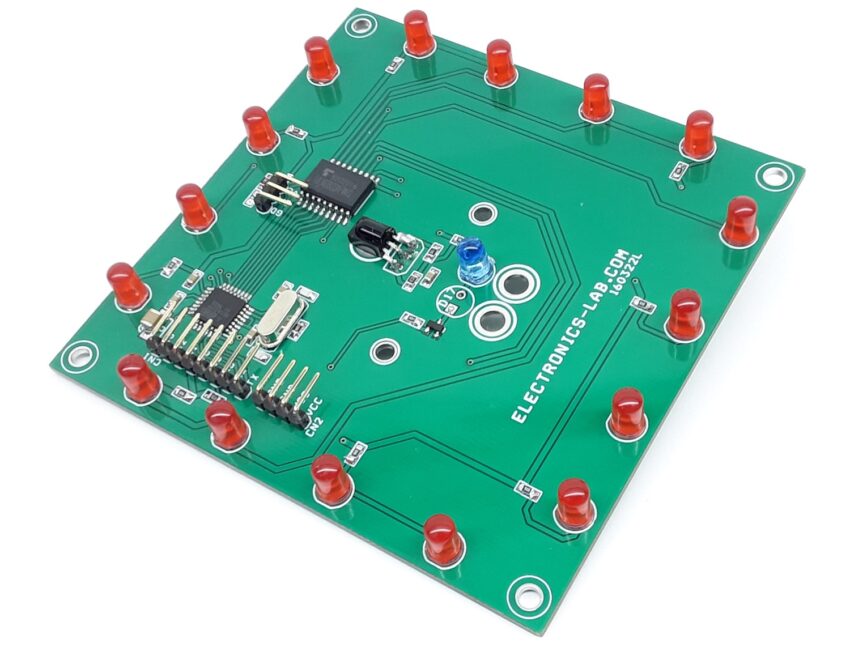
The project demonstrated here is an IR proximity sensor-based LED light, mainly designed for interactive coffee tables, but also can be used as single interactive light. The table can be made with multiple of these PCBs. Multiple tiles can be used as shown in the image below, each tile will light up when an object is placed over the sensor. Only the LEDs that are to the sensor area will light up. The project is Arduino compatible and consists of an ATMEGA328 chip, 16 x 5mm LEDs, ULN2803 multi-output driver for LEDs, IR Sensor, 5mm IR LED, and BC847 BJT transistor. The operating supply is 5V DC @ 200mA current.
Features
- Supply 5V DC @ 200mA
- 8 x LED Groups to Create Multiple LED effects
- On-Board IR LED
- Sensing Distance 2 cm to 15 cm
- On-Board IR Sensor
- PCB Dimensions 95.98 x 95.25mm
- 4 x 3mm Mounting Holes
Arduino Pins and Other Connections
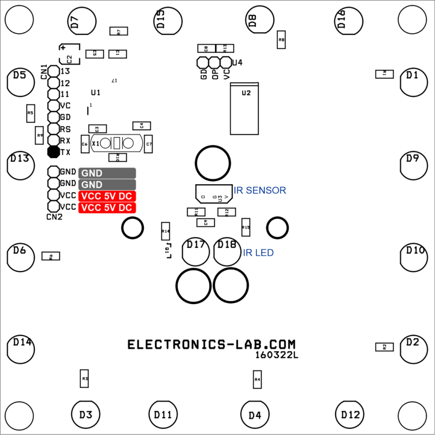
- Arduino Analog Pin A0 Optional analog Sensor Interface Connector U4
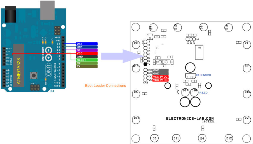
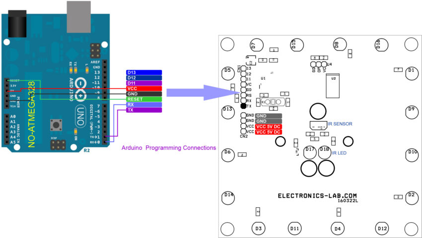
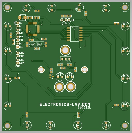
- CN1: Arduino Programming and Boot-Loader, Pin1 TX, Pin 2 RX, Pin 3 Reset, Pin 4 GND, Pin 5 VCC, Pin 6 D11, Pin 7 D12, Pin 8 D13
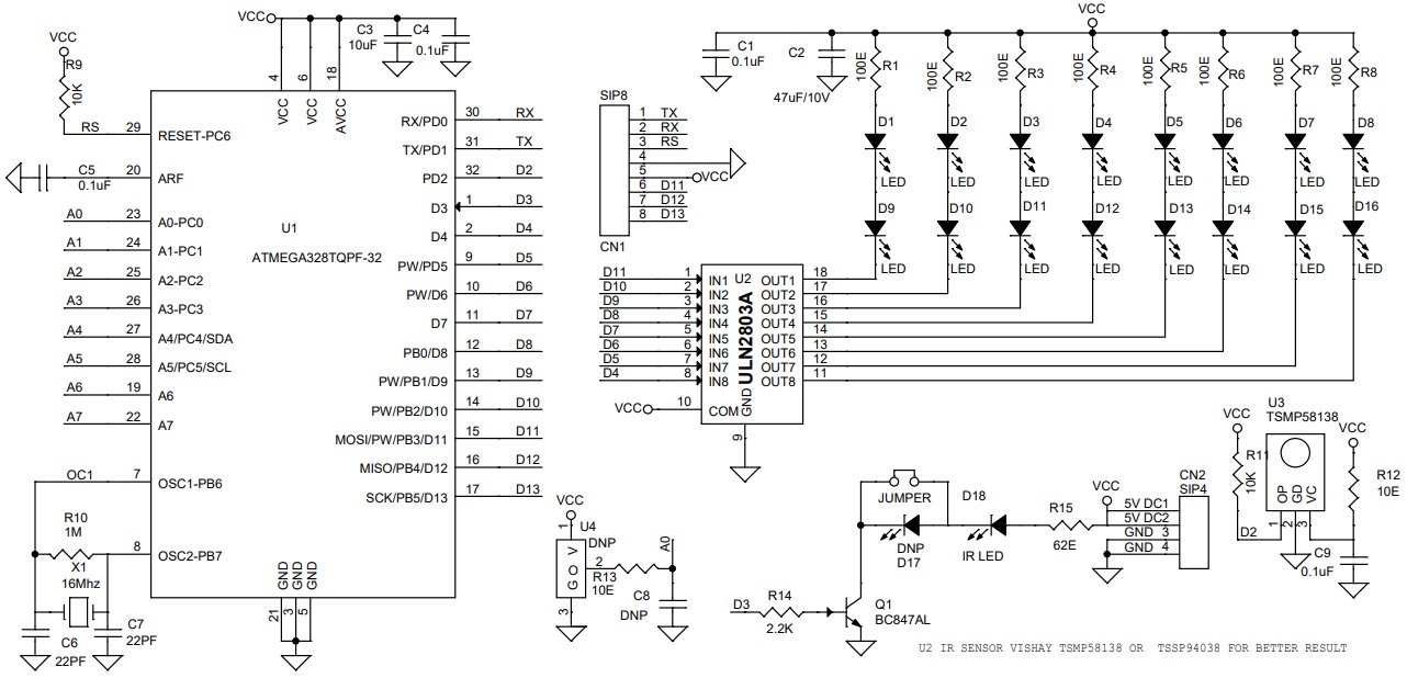
- Arduino Digital Pin D4 = LED 8 and LED 16
- Arduino Digital Pin D5 = LED 7 and LED 15
- Arduino Digital Pin D6 = LED 6 and LED 14
- Arduino Digital Pin D7 = LED 5 and LED 13
- Arduino Digital Pin D8 = LED 4 and LED 12
- Arduino Digital Pin D9 = LED 3 and LED 11
- Arduino Digital Pin D10 = LED 2 and LED 10
- Arduino Digital Pin D11 = LED 1 and LED 9
- Arduino Digital Pin D2 IR Sensor
- Arduino Digital Pin D3 IR LED
- CN2: Pin 1 VCC 5V DC, Pin 2 VCC 5V DC, Pin 3 GND, Pin 4 GND
Arduino Programming
Sample Arduino code is available as a download. The ATmega328 chip generates 38Khz pulses which drive the IR LED using a BC847 transistor, IR sensor is installed close to IR LED, When an object approaches the IR light, it reflects and falls on the IR sensor. IR sensor sends the signal to the ATMEGA328 chip and it drives all the outputs high, thus all LEDs are ON and continue in the same state until the object is removed. Refer to the connection diagram for bootloader burning and programming the ATMEGA chip with help of Arduino IDE. Users may write their own code as per requirements.
Schematic
Parts List
| NO | QNTY | REF | DESC | MANUFACTURER | PART NO |
|---|---|---|---|---|---|
| 1 | 1 | CN1 | 8 PIN MALE HEADER RIGHT ANGLE PITCH 2.54MM | WURTH | 732-5321-ND |
| 2 | 1 | CN2 | 4 PIN MALE HEADER RIGHT ANGLE PITCH 2.54MM | WURTH | 732-5317-ND |
| 3 | 4 | C1,C4,C5,C9 | 0.1uF/10V CERAMIC SMD SIZE 0805 | YAGEO/MURATA | |
| 4 | 1 | C2 | 47uF/10V CERAMIC SMD SIZE 1210 | YAGEO/MURATA | |
| 5 | 1 | C3 | 10uF/10V CERAMIC SMD SIZE 0805 | YAGEO/MURATA | |
| 6 | 2 | C6,C7 | 22PF/50V CERAMIC SMD SIZE 0805 | YAGEO/MURATA | |
| 7 | 3 | U4,C8,D17 | DNP | ||
| 8 | 16 | D1 TO D16 | 5MM RED LED OR GREEN | SUNLED | 1497-XCMDK12D-ND |
| 9 | 1 | D18 | IR LED 5MM | KINGBRIGHT | 754-2222-ND |
| 10 | 1 | J1 | WIRE JUMPER JUMPER | WIRE JUMPER | |
| 11 | 1 | Q1 | BC847AL | NEXPERIA | 1727-2924-2-ND |
| 12 | 8 | R1,R2,R3,R4,R5,R6,R7,R8 | 100E 5% SMD SIZE 0805 | YAGEO/MURATA | |
| 13 | 2 | R9,R11 | 10K 5% SMD SIZE 0805 | YAGEO/MURATA | |
| 14 | 1 | R10 | 1M 5% SMD SIZE 0805 | YAGEO/MURATA | |
| 15 | 2 | R12,R13 | 10E 5% SMD SIZE 0805 | YAGEO/MURATA | |
| 16 | 1 | R14 | 2.2K 5% SMD SIZE 0805 | YAGEO/MURATA | |
| 17 | 1 | R15 | 62E 5% SMD SIZE 0805 | YAGEO/MURATA | |
| 18 | 1 | U1 | ATMEGA328TQPF-32 | MICROCHIP | ATMEGA328PB-AURCT-ND |
| 19 | 1 | U2 | ULN2803A | TI | ULN2803ADW-ND |
| 20 | 1 | U3 | TSMP58138 | VISHAY | TSMP58138 |
| 21 | 1 | X1 | 16Mhz | ECS INC | X1103-ND |
Connections
Installation
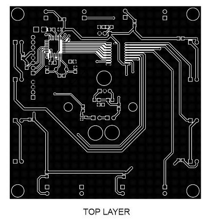
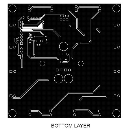
Gerber View
Photos
Video


