DC Motor IR2104 H-BRIDGE
- Rajkumar Sharma
- 41.073 Views
- medium
- Tested
- SKU: EL46373
- Quote Now
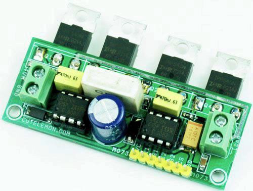
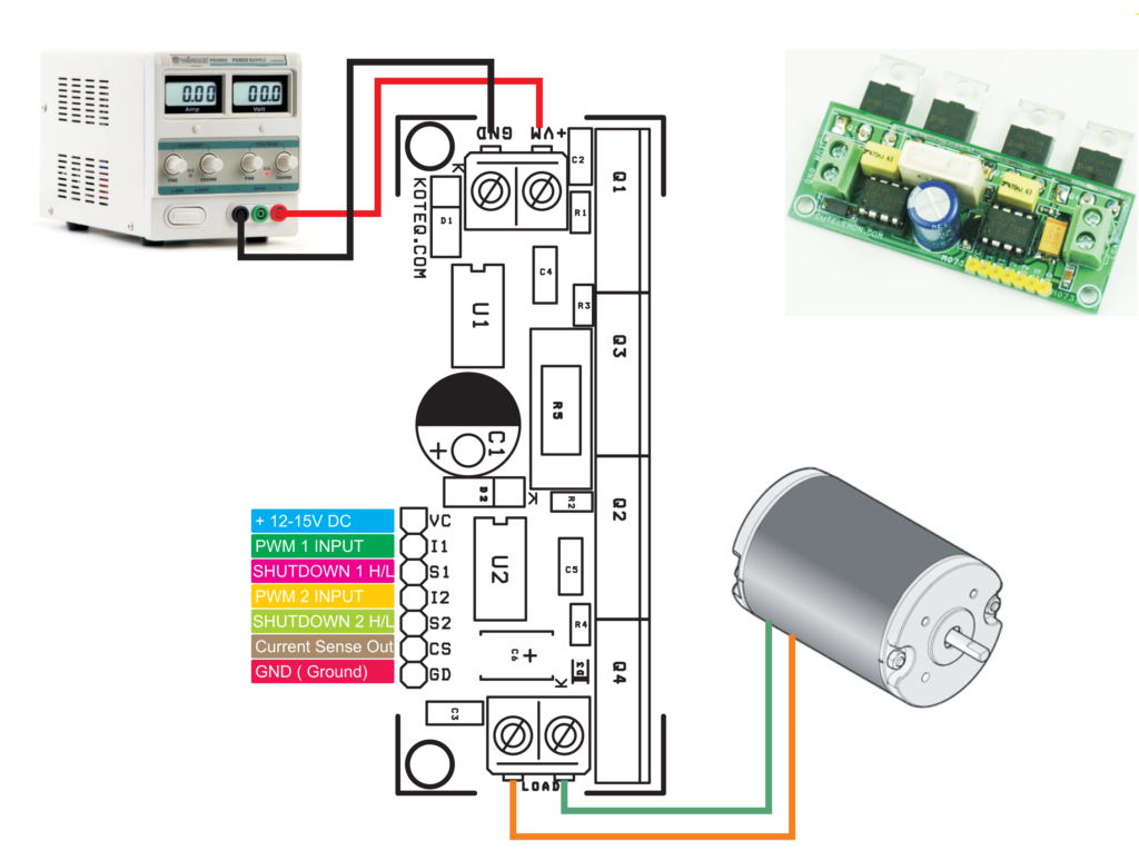
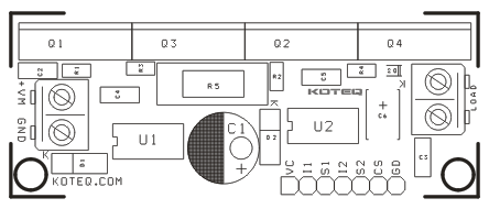
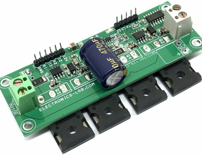
H-Bridge has been designed around IR2104 IC from International Rectifier. The board has been made mainly for DC-Motor applications. The driver can handle a load up to 8-10Amps. I have tested this board with 36V DC supply . The circuit also uses N Channel IR540 MOSFETS from International rectifier. IR540 requires large heat sink for 10Amps load. Board has shunt resistor to provide voltage proportional to current flowing through load. This can be later amplified and read from microcontroller ADC. This H-bridge can be used to control DC Motor speed and direction, DC-DC Converters, HMI lamp driver etc.
Features
- Motor DC Supply 36V DC (Screw Terminal Connector)
- Logic Supply 12V DC
- Load 8-10Amps (Screw Terminal Connector)
- Header Connector for Inputs (7 Pin Header Connector)
- On Board Shunt Resistor for Current feedback
- PWM Frequency 10 to 20 KHz
- Duty Cycle 0-99%
- Logic Pins support 3.3V, 5V, 12V (Inputs and PWM)
Schematic
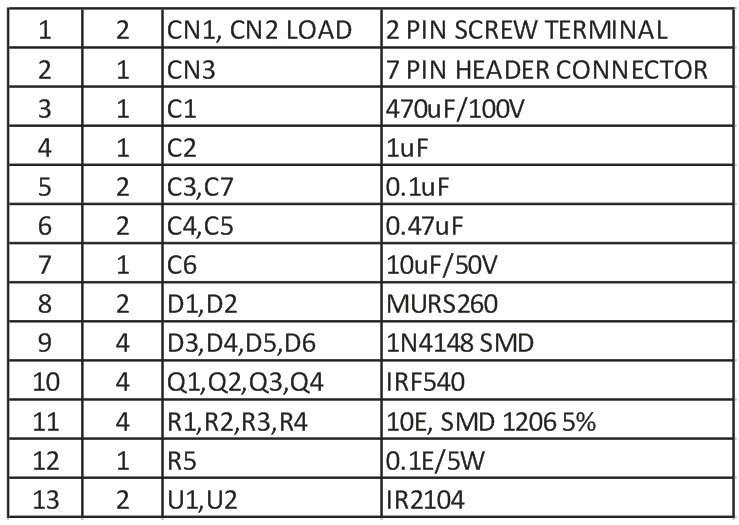
Parts List
Connection Diagram / Waveforms
To drive the H-Bridge you will need a microcontroller or Arduino board to produce a PWM wave with frequency 20Khz and adjustable 0-99% Duty Cycle.
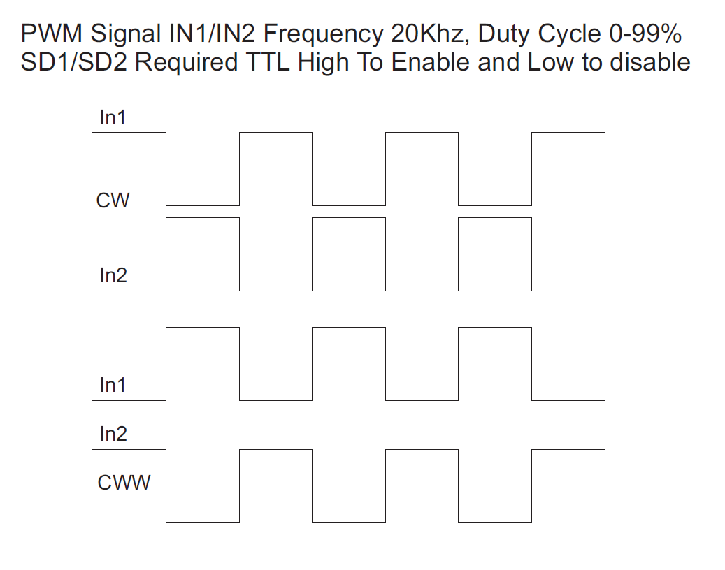
For Forwarding Direction Operation:
- IN1 Requires High PWM
- IN2 Requires Low PWM
For Reverse Direction Operation:
- IN1 Requires Low PWM
- IN2 Requires High PWM
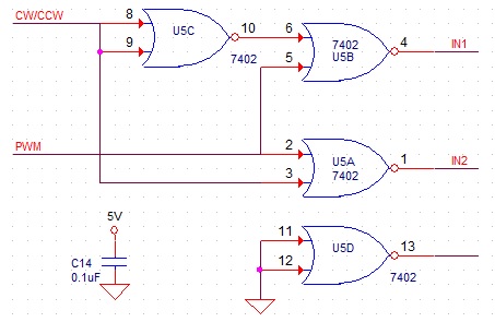
For Standalone use you will need a PWM Generator and pulse sequencer circuit, please find attached sequencer circuit.



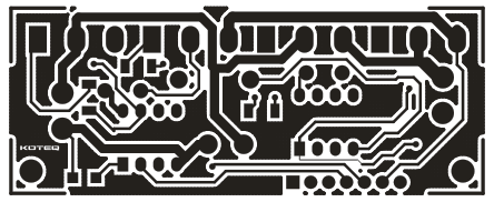
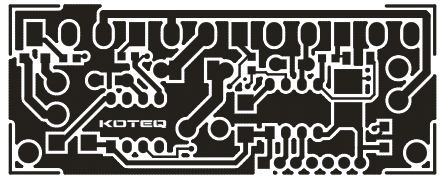


Can I buy that raw PCB anywhere?
Please check on http://www.koteq.com for kits of our projects.
Can you please share receiver connection ?
Which connection diagram do you mean?
pleas how i can control by the driver using arduino (how i can generate inverting pwm signal and how i can control in first state high or low)
Hi there! Could you give me some advice? I would like to build simple DC motor speed regulator. I have 130V DC motor with encoder. I consider 2 options:
a) use 2 relays for direction/ movement controll and PWM regulator for speed controll
b) build full H-bridge (like this one) but for much higher suply voltage.
I would like do it as simple as possible,wich one option you preffer? If the best is (b) could I replece just Q1-Q4 and C1 for 130V DC power suply? IR2104 is for 600VDC 🙂
Best’s
Karol
Hello,
Can you please tell what is the driving principle?
Hi, I have uploaded the waveforms needed to be present in IN1 and IN2 to control the motor in forward and reverse operation. In general an H-bridge can be used to control the direction and speed of a motor and this particular one need 2x PWM signals 20KHz with adjustable duty cycle.
How can I increase the load that their drivers can handle?
This motor driver can output a maximum of 8-10A current. Unfortunately this is the maximum output power. For more power you will need a different circuit.
Hi,
I need to run this using 100kHz PWM signal. What are the necessary adjustments for same.
Thanks with regards
Gamini
This board can be driven by PWM frequenxy from 10kHz to 20Khz, it is not possible to drive it with 100kHz, unless you divide the frequency by 10.
why ı cant use over 20khz and how ı can use.
Probably the IC will not handle that, do you mind checking the datasheet? Otherwise, you can try it on real conditions.
why ı cant use over 20khz and how ı can use.