


This is the image preview of the following page:
[Customadds id=643821] Description The above pictured schematic diagram is just a standard constant current model with a added current limiter, consisting of Q1, R1, and R4. The moment too much current is flowing biases Q1 and drops the output voltage. The output voltage is: 1.2 x (P1+R2+R3... Read More
Image Downloads:
- full (294x167)
- thumbnail (150x150)
- medium (294x167)
- medium_large (294x167)
- large (294x167)
- 1536x1536 (294x167)
- 2048x2048 (294x167)
- re_large (294x167)
- re_xxmedium (290x167)
- re_xmedium (294x167)
- re_medium (294x167)
- re_a_xsmall (186x167)
- re_xsmall (125x96)
- crp_thumbnail (292x167)
- menu-24x24 (24x14)
- menu-36x36 (36x20)
- menu-48x48 (48x27)
- sendpress-max (294x167)
- woocommerce_thumbnail (294x167)
- woocommerce_single (294x167)
- woocommerce_gallery_thumbnail (100x100)
- wp_rp_thumbnail (150x150)
- wp_rp_thumbnail_prop (150x85)
RELATED POSTS
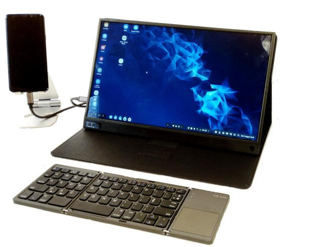 24 September, 2019 Sm@rtDock 15 Touch is a 15″ 2-in-1 Laptop Dock for Samsung DeX Devices and Smartphones with a USB-C Port
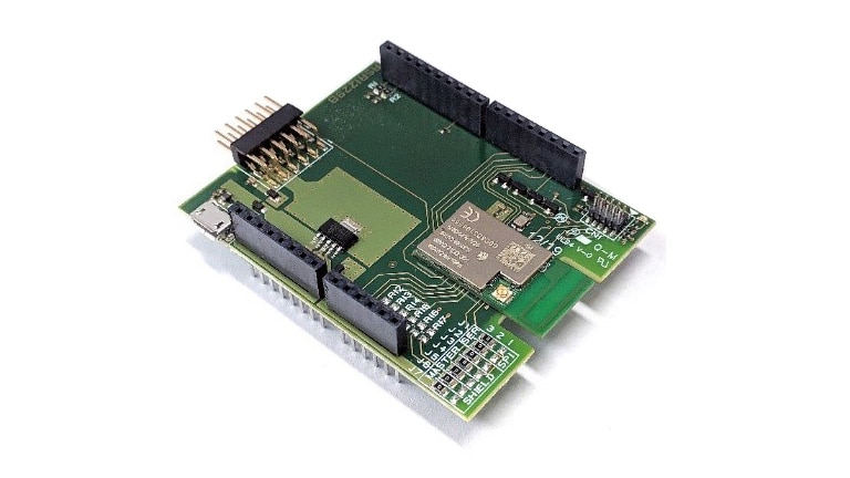 10 June, 2019 Avnet Silica WiFi Shield based on AW-Cu300A module
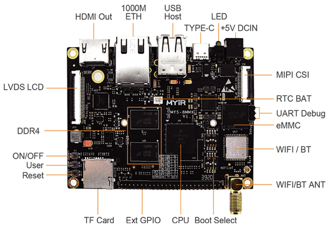 23 April, 2021 Low-cost i.MX 8M Mini SBC with Advanced Video and Graphics Capabilities
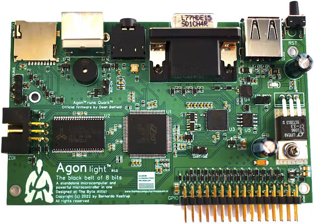 4 January, 2023 Agon Light is a Fully Open-Source 8-bit Microcomputer and Microcontroller
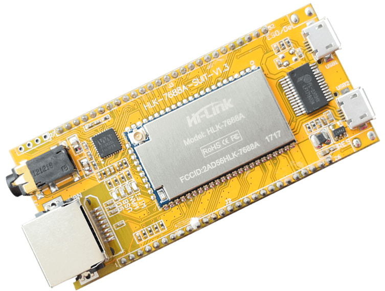 7 November, 2019 HLK-7688A OpenWrt Development Board Comes with an Audio Jack
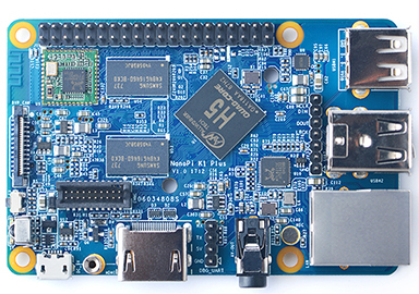 27 April, 2018 NanoPi K1 Plus – A New Open-spec SBC By FriendlyElec Powered By Allwinner H5 SoC


