MC33035 Brushless motor driver breakout board
- Rajkumar Sharma
- 24.371 Views
- medium
- Tested
- SKU: EL72165
- Quote Now
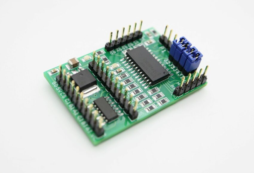
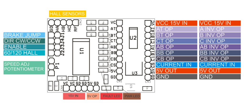
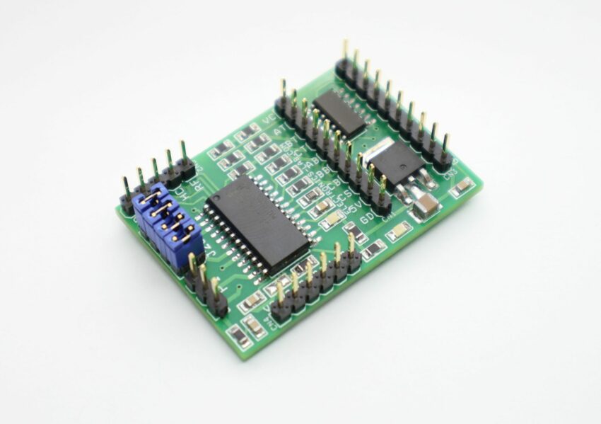
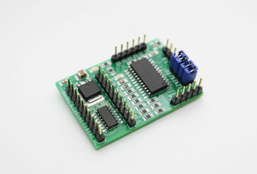
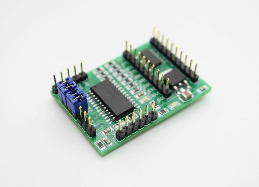
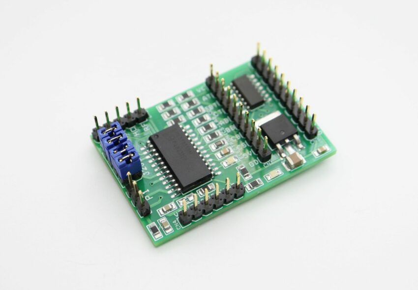
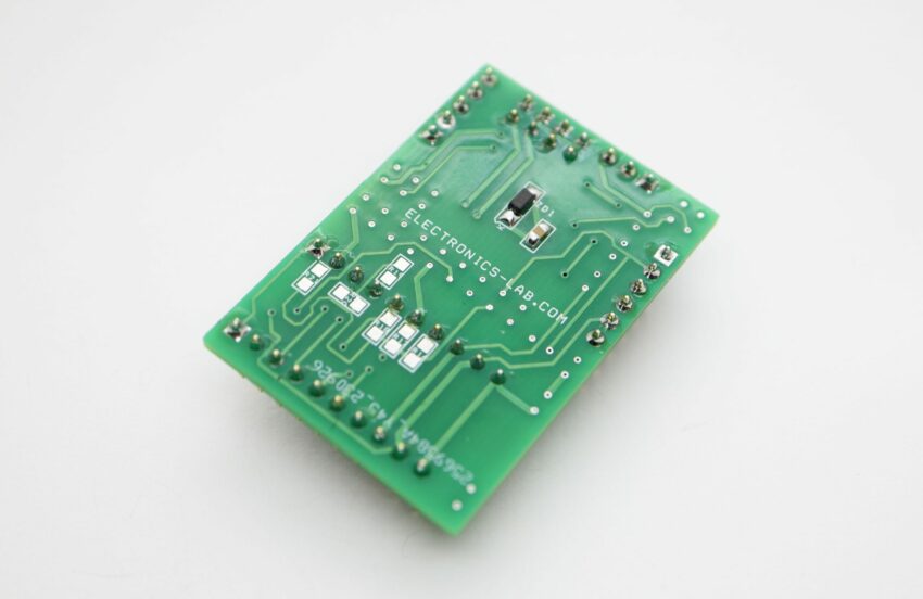
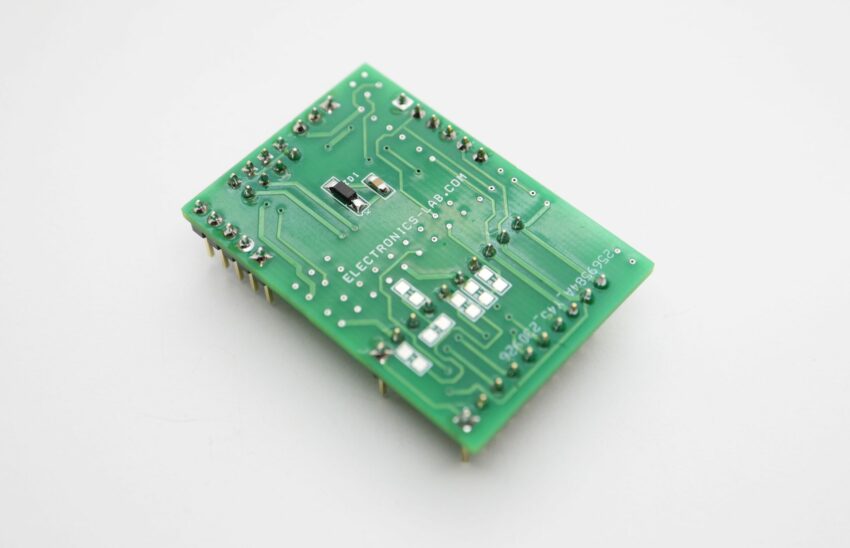
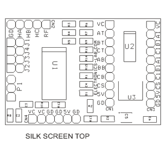
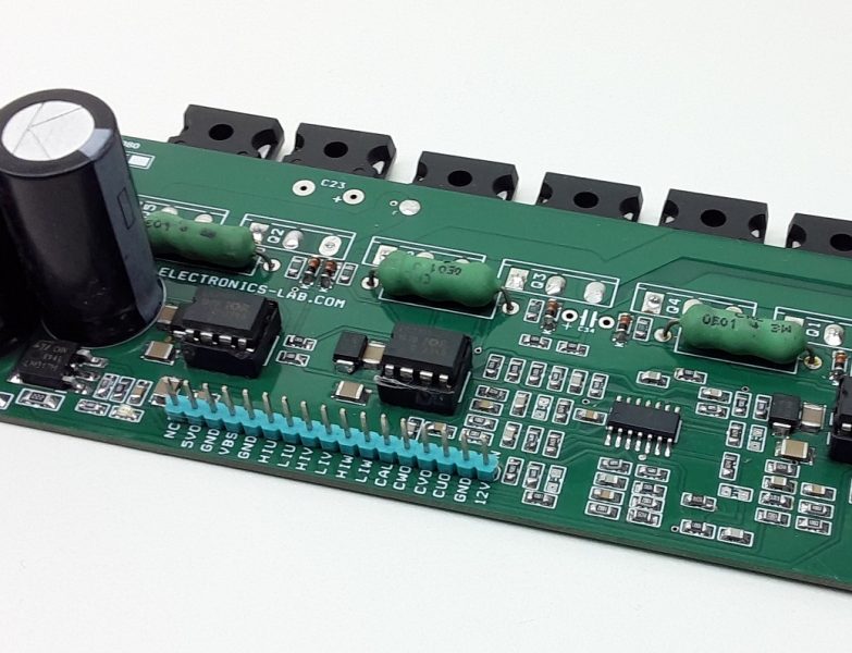
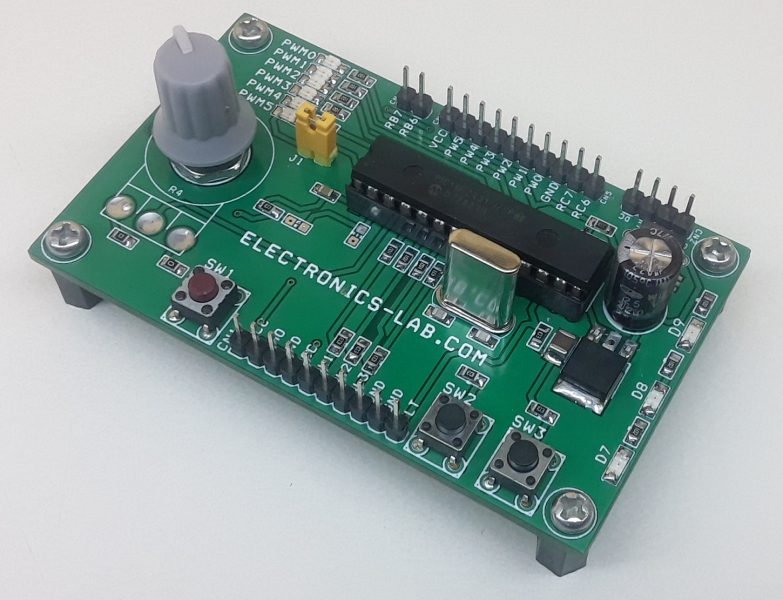
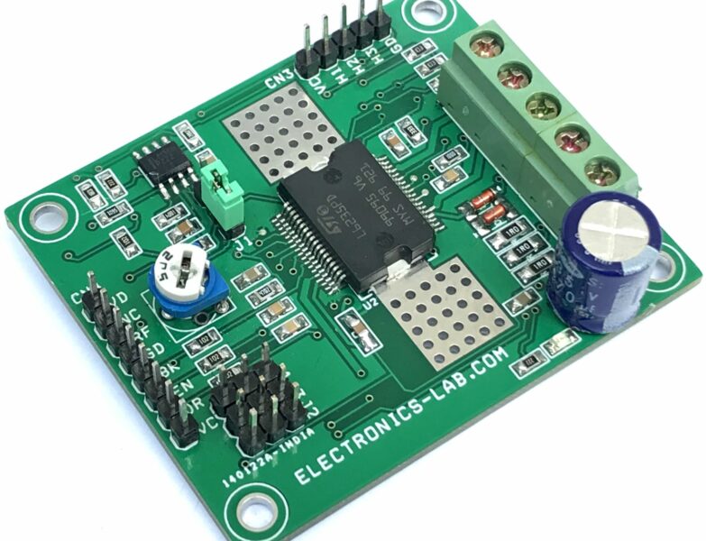
The board shown here is a breakout board for MC33035 brushless motor controller. It requires an output buffer IPM module or MOSFETs to complete a closed-loop brushless motor driver circuit. MC33035 IC is the heart of the project. The board provides 6 PWM pulses as well as 6 Inverse pulse outputs. On-board Jumpers help to change the Direction, Enable, Brake, and 60/120 phasing. A header connector is provided to connect the Hall sensors and supply, onboard LED for Power and fault indication, and a P1 potentiometer helps to change the motor speed.
MC33035 Brushless DC Motor Controller
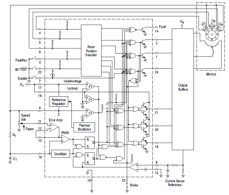
The MC33035 is a high-performance second-generation monolithic brushless DC motor controller containing all of the active functions required to implement a full-featured open loop, three or four-phase motor control system. This device consists of a rotor position decoder for proper commutation sequencing, temperature compensated reference capable of supplying sensor power, frequency programmable sawtooth oscillator, three open collector top drivers, and three high current totem pole bottom drivers ideally suited for driving power MOSFETs. Also included are protective features consisting of under voltage lockout, cycle−by−cycle current limiting with a selectable time-delayed latched shutdown mode, internal thermal shutdown, and a unique fault output that can be interfaced into microprocessor-controlled systems. Typical motor control functions include open loop speed, forward or reverse direction, run enable, and dynamic braking. The MC33035 is designed to operate with electrical sensor phasings of 60°/300° or 120°/240°, and can also efficiently control brush DC motors.
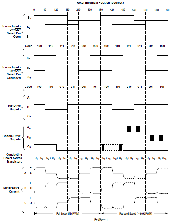
An internal rotor position decoder monitors the three sensor inputs (Pins 4, 5, 6) to provide the proper sequencing of the top and bottom drive outputs. The sensor inputs are designed to interface directly with open collector-type Hall Effect switches or opto-slotted couplers. Internal pull−up resistors are included to minimize the required number of external components. The inputs are TTL compatible, with their thresholds typically at 2.2 V. The MC33035 series is designed to control three-phase motors and operate with four of the most common conventions of sensor phasing. A 60°/120° Select (Pin 22) is conveniently provided and affords the MC33035 to configure itself to control motors having either 60°, 120°, 240° or 300° electrical sensor phasing. With three sensor inputs, there are eight possible input code combinations, six of which are valid rotor positions. The remaining two codes are invalid and are usually caused by an open or shorted sensor line. With six valid input codes, the decoder can resolve the motor rotor position to within a window of 60 electrical degrees. The Forward/Reverse input (Pin 3) is used to change the direction of motor rotation by reversing the voltage across the stator winding. When the input changes state, from high to low with a given sensor input code (for example 100), the enabled top and bottom drive outputs with the same alpha designation are exchanged (AT to AB, BT to BB, CT to CB). In effect, the commutation sequence is reversed and the motor changes directional rotation.
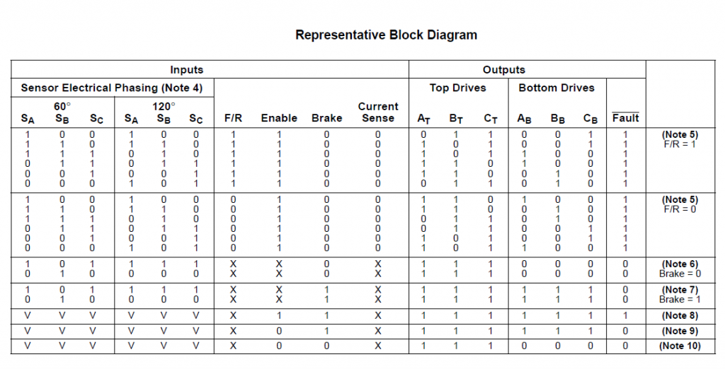
Motor on/off control is accomplished by the Output Enable (Pin 7). When left disconnected, an internal 25 mA current source enables sequencing of the top and bottom drive outputs. When grounded, the top drive outputs turn off and the bottom drives are forced low, causing the motor to coast and the Fault output to activate. Dynamic motor braking allows an additional margin of safety to be designed into the final product. Braking is accomplished by placing the Brake Input (Pin 23) in a high state. This causes the top drive outputs to turn off and the bottom drives to turn on, shorting the motor−generated back EMF. The brake input has unconditional priority over all other inputs. The internal 40 kΩ pull−up resistor simplifies interfacing with the system safety switch by ensuring brake activation if opened or disconnected. The commutation logic truth table is shown in Figure 20. A four-input NOR gate is used to monitor the brake input and the inputs to the three top drive output transistors. Its purpose is to disable braking until the top drive outputs attain a high state. This helps to prevent simultaneous conduction of the top and bottom power switches. In half-wave motor drive applications, the top drive outputs are not required and are normally left disconnected. Under these conditions braking will still be accomplished since the NOR gate senses the base voltage to the top drive output transistors.
Continuous operation of a motor that is severely overloaded results in overheating and eventual failure. This destructive condition can best be prevented with the use of cycle−by−cycle current limiting. That is, each on−cycle is treated as a separate event. Cycle−by−cycle current limiting is accomplished by monitoring the stator current build−up each time an output switch conducts, and upon sensing an over-current condition, immediately turning off the switch and holding it off for the remaining duration of the oscillator ramp−up period. The stator current is converted to a voltage by inserting a ground−referenced sense resistor. The voltage developed across the sense resistor is monitored by the Current Sense Input (Pins 9 and 15), and compared to the internal 100 mV reference. The current sense comparator inputs have an input common mode range of approximately 3.0 V. If the 100 mV current sense threshold is exceeded, the comparator resets the lower sense latch and terminates output switch conduction. The value for the current sense resistor is:
RS=0.1/ Istator(max)
The Fault output activates during an over-current condition. The dual−latch PWM configuration ensures that only one single output conduction pulse occurs during any given oscillator cycle, whether terminated by the output of the error amp or the current limit comparator.
Specifications
- Supply 12-18V
- Jumpers for Direction, Enable,60/120 Phasing, Brake
- LED D1 Fault
- LED D2 Power LED
- Pot P1 Speed Control
- CN1 6 PWM Outputs
- CN3 6 Inverse PWM Outputs
- CN4 Supply Input
- CN2 Hall Sensor Interface
- Frequency 18 KHz
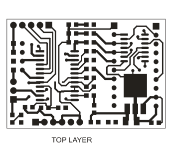
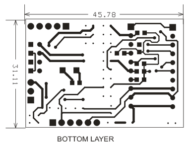
- PCB dimensions: 31.11 x 45.78 mm
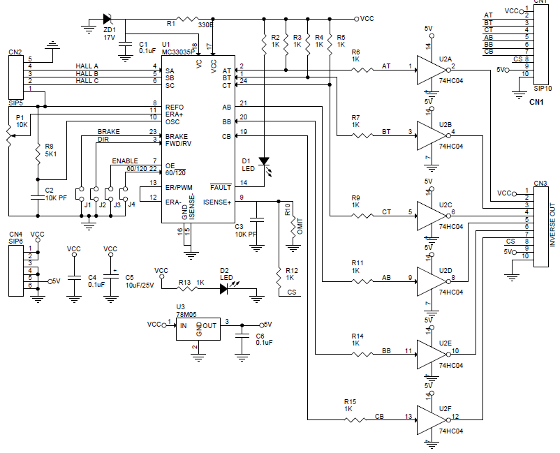
Schematic
Parts List
| SR. | QNTY. | REF. | DESC. |
|---|---|---|---|
| 1 | 1 | CN1 | 10 PIN HEADER CONNECTOR |
| 2 | 1 | CN2 | 5 PIN HEADER CONNECTOR |
| 3 | 1 | CN3 | 10 PIN HEADER CONNECTOR |
| 4 | 1 | CN4 | 6 PIN HEADER CONNECTOR |
| 5 | 3 | C1, C4, C6 | 0.1uF SMD 0805 |
| 6 | 2 | C2,C3 | 10K PF SMD 0805 |
| 7 | 1 | C5 | 10uF/25V SMD 1210 |
| 8 | 2 | D1, D2 | LED SMD 0805 |
| 9 | 4 | J1, J2, J3, J4 | 2PIN HEADER |
| 10 | 1 | P1 | 10K POTENTIOMETER |
| 11 | 1 | R1 | 330E SMD 0805 |
| 12 | 12 | R2 to R7, R9 , R11 to R15 | 1K SMD 0805 |
| 13 | 1 | R8 | 5K1 SMD 0805 |
| 14 | 1 | R10 | OMIT |
| 15 | 1 | U1 | MC33035P SMD |
| 16 | 1 | U2 | 74HC04 SMD |
| 17 | 1 | U3 | 78M05 SMD DPAK |
| 18 | 1 | ZD1 | 17V ZENER SMD |
| 19 | 6 | R16 to R21 | don't place |




Could it drive BLDC Controller with voltage 36V 350W? Thanks
It depends on the output buffer you will use. This board will only produce the required control signals and you need to use a power output stage.
Do you sell it the boards? May I know the dimension of this boards ?
Can you build a BLDC motor driver based on UCC3626 ?
Yes, we have a project based on UCCC3626 which will be published on our website soon.
need to buy mc33035 breakout board. where to buy?
Please email me through the form here: https://www.electronics-lab.com/contact-us/
Sir this can use for ipm control
Yes, It requires an output buffer IPM module or MOSFETS to complete the closed loop brushless motor driver.
Hi
Thanks for this superb article. Can i request you to suggest a suitable output buffer module to run a 350w bldc motor namely, the generic hoverboard motor. Also please send me source to buy the pcbs. Kaleemulla
What is the price of this drive and delivery,please.
Mc33039 motor driver how can use interface optocoupler to control 220vdc treadmill motor at constant speed all the time
Hello,
Is this board commercially available ?
We have a BOMA brushless BLDC motor, 48 VDC, 1000 Watt.
Three phase, nine coils, three Hall effect sensors placed in three consecutive stator slots, and 40 degrees spaced each.
We know how to select and build the power stage,
But we would need a way to properly identify Hall and power wiring in the motor.
Thanks for you help,
Horacio Berardone Bouhebent
Civil Engineer
Hi there
Can You suggest me a suitable mosfet in order to control a 20W 24V bldc motor?