Measuring Water Flow Rate and Volume using Arduino and a Flow Sensor
- Emmanuel Odunlade
- https://twitter.com/emmaodunlade
- emmaodunlade@gmail.com
- 15.379 Views
- easy
- Tested
Flow rate and volume helps tell the amount of fluid going into, or through a particular vessel. For certain process automation applications, this simple-sounding fluid measurement task is so critical to the success of the project that, failure to get it right, could bring the entire process to its knees. This is why for today’s tutorial, I thought it will be cool to look at this nice water flow sensor; the YF-S201, and its use in an Arduino based project.
The YF-S201 water flow sensor consists of a pinwheel sensor that measures the quantity of liquid passing through it.
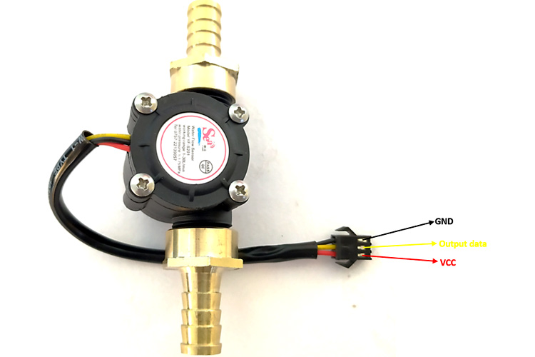
The sensor uses the principles of electromagnetism, such that, when liquids flow through the sensor, the flow action impacts the fins of a turbine in the sensor, causing the wheel to spin. The shaft of the turbine wheel is connected to a hall effect sensor so that with every spin, a pulse is generated, and by monitoring that pulse with a microcontroller, the sensor can be used in determining the volume of fluid passing through it.
As the microcontroller for today, we will use the Arduino Uno. The Uno will be used to count the number of pulses detected over time and calculate the flow rate (in liters/hour) and total volume of fluid that has passed through it using the total number of pulses. The result, flow rate and volume, will then be displayed on a 16×2 LCD so as to provide a visual feedback to the user. If the 16×2 LCD is not available, you can view the data over the Arduino Serial Monitor.
At the end this tutorial, you would know how to use the YF-S201 flow sensor with the Arduino.
Required Components
The following components are required to build this project:
- YF-S201 Water Flow Sensor
- Arduino UNO (or any other compatible board)
- 16×2 LCD Display
- Jumper Wires
- Breadboard
- Power Bank or Battery Pack.
Schematics
Connect the components as shown in the schematics below:
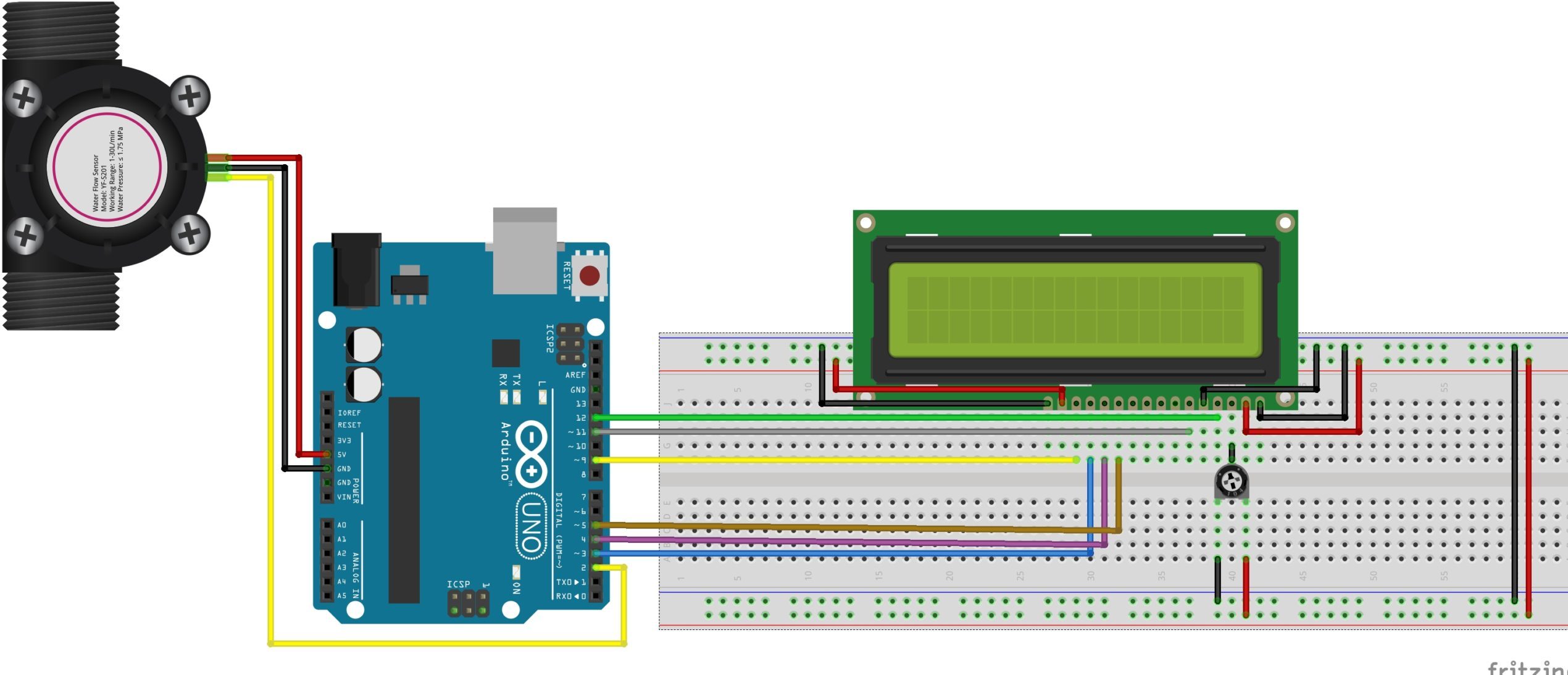
To make reading the sensor and calculating flow easy, the interrupt feature of the Atmega328p on the Ardunio is employed, as such, the signal pin of the YF-S201 is connected to one of the interrupt-enabled IOs of the Uno (in this case, pin D2). The LCD, on the other hand, is connected in a 4-bit mode to the Arduino. To save some time on connections, you could also decide to use an I2C enabled version of the 16×2 LCD display. For this, you will only need to connect 4 wires from the display to the Arduino. It will, however, call for some modification in the code, so be sure you can handle it before making that decision.
A breakdown of the connection showing how the components are connected, pin-to-pin, is provided below;
YF-S201 – Arduino Uno
VCC(red wire) - 5V
GND(Black wire) - GND
Signal(Yellow wire) - A0
LCD – Arduino Uno
Vss - GND
Vdd - 5V
V0 - (Connect to middle point of potentiometer)
RS - D12
RW- GND
E - D11
D7 - D9
D6 - D3
D5 - D4
D4 - D5
LED+ - 5V
LED - GND
To better understand the LCD connections, you can check out this tutorial we wrote a while back on interfacing 16×2 LCD Displays with Arduino boards.
Double-check the connections to make sure everything is as it should be before proceeding to the next section.
Code
The idea behind the sketch is simple: monitor the signal pin of the YF-S201 to detect when the hall sensor is triggered (flow is detected) and increment a variable to show the increased inflow. However, to do that efficiently and accurately, we will use the interrupt feature of the Arduino such that whenever the hall sensor detects the rotating magnet, a rising edge interrupt is fired and registered by the Arduino. The total number of interrupts fired over a particular time is then used in generating the flowrate and the total volume of liquid that has traveled through the flow meter.
Since the flow determination is pretty straight forward, the only library we will use for this tutorial is the Arduino Liquid Crystal library. The library contains functions that make it easy to interface the 16×2 LCD with an Arduino. The library is included with the Arduino IDE but in case it’s not, it can be installed via the Arduino IDE Library Manager.
With the library installed, we then move to write the Arduino Sketch for the project.
As usual, I will go over the code and explain parts of it.
The code starts with the inclusion of the Liquid crystal library:
#include <LiquidCrystal.h>
It is followed by the declaration of some variables that will be used to store data later and the creation of an instance of the liquid crystal library.
volatile int flow_frequency; // Measures flow sensor pulses
float vol = 0.0,l_minute;
unsigned char flowsensor = 2; // Sensor Input
unsigned long currentTime;
unsigned long cloopTime;
LiquidCrystal lcd(12, 11, 5, 4, 3, 9);
Next, we create the flow() function. This function is called whenever the interrupt is detected and it will increment the flow counter which will serve as an indication of the flow rate.
void flow () // Interrupt function
{
   flow_frequency++;
}
Next, we write the void setup() function. We start the function by including initializing serial communication so as to have access to the serial monitor for debugging purposes.
Serial.begin(9600);
Next, we declare the Arduino pin to which the signal pin of the flow sensor is connected, as an input pin. We create a pull-up on the pin by setting it “HIGH” and set up a “Rising” edge interrupt on it with the flow() function we created earlier as the callback.
pinMode(flowsensor, INPUT);
digitalWrite(flowsensor, HIGH); // Optional Internal Pull-Up
attachInterrupt(digitalPinToInterrupt(flowsensor), flow, RISING); // Setup Interrupt
Next, we initialize the LCD and display a few words to create an effect similar to the splash screen in mobile apps.
lcd.begin(16, 2);
lcd.clear();
lcd.setCursor(0,0);
lcd.print("Arduino Flow Meter");
lcd.setCursor(0,1);
lcd.print("v1.0");
We wrap up the setup function by calling the millis() function to keep track of the time since flow rate as a measure of the flow within a particular time frame.
 currentTime = millis();
   cloopTime = currentTime;
}
Next, we write the void loop() function.
The loop starts by comparing how much time has elapsed since the last loop. The flow frequency, obtained via the interrupt action, is then divided by time (in minutes) and the value is displayed as the flowrate. The value is also added to the existing volume(vol) and displayed as the total volume of fluid that has passed through the sensor.
void loop ()
{
   currentTime = millis();
   // Every second, calculate and print litres/hour
   if(currentTime >= (cloopTime + 1000))
   {
    cloopTime = currentTime; // Updates cloopTime
    if(flow_frequency != 0){
      // Pulse frequency (Hz) = 7.5Q, Q is flow rate in L/min.
      l_minute = (flow_frequency / 7.5); // (Pulse frequency x 60 min) / 7.5Q = flowrate in L/hour
      lcd.clear();
      lcd.setCursor(0,0);
      lcd.print("Rate: ");
      lcd.print(l_minute);
      lcd.print(" L/M");
      l_minute = l_minute/60;
      lcd.setCursor(0,1);
      vol = vol +l_minute;
      lcd.print("Vol:");
      lcd.print(vol);
      lcd.print(" L");
      flow_frequency = 0; // Reset Counter
      Serial.print(l_minute, DEC); // Print litres/hour
      Serial.println(" L/Sec");
    }
If the interrupt wasn’t triggered during the entire duration, zero is displayed on the LCD.
   else {
      Serial.println(" flow rate = 0 ");
      lcd.clear();
      lcd.setCursor(0,0);
      lcd.print("Rate: ");
      lcd.print( flow_frequency );
      lcd.print(" L/M");
      lcd.setCursor(0,1);
      lcd.print("Vol:");
      lcd.print(vol);
      lcd.print(" L");
    }
   }
}
The loop goes on and the value increases till the project is disconnected from power.
The complete sketch is provided below and also attached under the download section.
#include <LiquidCrystal.h>

float vol = 0.0,l_minute;
unsigned char flowsensor = 2; // Sensor Input
unsigned long currentTime;
unsigned long cloopTime;

LiquidCrystal lcd(12, 11, 5, 4, 3, 9);

void flow () // Interrupt function to increment flow
{
   flow_frequency++;
}
void setup()
{
   Serial.begin(9600);
   pinMode(flowsensor, INPUT);
   digitalWrite(flowsensor, HIGH); // Optional Internal Pull-Up
   attachInterrupt(digitalPinToInterrupt(flowsensor), flow, RISING); // Setup Interrupt

   lcd.begin(16, 2);
   lcd.clear();
   lcd.setCursor(0,0);
   lcd.print("Arduino FlowMeter");
   lcd.setCursor(0,1);
   lcd.print("v1.0");
   currentTime = millis();
   cloopTime = currentTime;
}

void loop ()
{
   currentTime = millis();
   // Every second, calculate and print litres/hour
   if(currentTime >= (cloopTime + 1000))
   {
    cloopTime = currentTime; // Updates cloopTime
    if(flow_frequency != 0)
    {

       l_minute = (flow_frequency / 7.5); // (Pulse frequency x 60 min) / 7.5Q = flowrate in L/hour
      lcd.clear();
      lcd.setCursor(0,0);
      lcd.print("Rate: ");
      lcd.print(l_minute);
      lcd.print(" L/M");
      l_minute = l_minute/60;
      lcd.setCursor(0,1);
      vol = vol +l_minute;
      lcd.print("Vol:");
      lcd.print(vol);
      lcd.print(" L");
      flow_frequency = 0; // Reset Counter
      Serial.print(l_minute, DEC); // Print litres/hour
      Serial.println(" L/Sec");
    }
    else {
      Serial.println(" flow rate = 0 ");
      lcd.clear();
      lcd.setCursor(0,0);
      lcd.print("Rate: ");
      lcd.print( flow_frequency );
      lcd.print(" L/M");
      lcd.setCursor(0,1);
      lcd.print("Vol:");
      lcd.print(vol);
      lcd.print(" L");
    }
   }
}
Demo
Go over your connections to be sure everything is as it should be. With this done and the code complete, connect the hardware to your computer and upload the code to the Arduino board. If successful, you should see the display come up as shown in the image below.
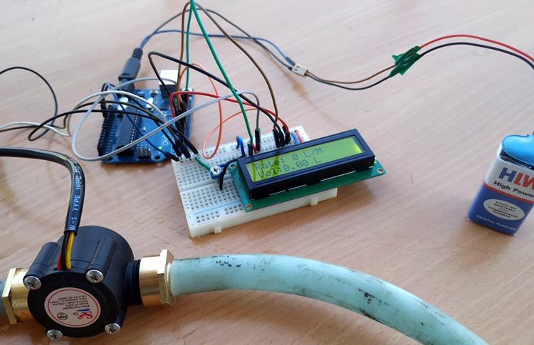
Connect some pipes to it using whatever means is easy for you and pass some water through the flow sensor. You should see the flowrate being displayed on your screen, vary with the intensity of water flow, and you should also see the volume increase as more water flows through it.
If you don’t have the tubes/pipes for water around at that instant, you can blow some air into the sensor. You should hear the rotor in spin and the values on the LCD should increase.
Flowrate/ volume metering is a very important part of several industrial and even individual consumer processes. It provides to not only monitor consumption but also meter supply and I believe applications like smart water meters and automated fluid dispensers should give you tons of insights into how this seemingly basic project could be transformed into an amazing super useful product.
That’s it! feel free to reach me via the comments section for help with any challenge you might have replicating the project.


Awesome Code! Congratulations. Just a little correction in line 55. It would be L/h not L/Sec. Have a nice day!
brother i have a small doubt in this code…. from where these two commands came— unsigned long currentTime;
unsigned long cloopTime; ? what is the meaning for this commands? please tell me…
and one more thing is why we are making the sensor pin high? digitalWrite(flowsensor, HIGH);
Hi M.S.
They are used to keep track of time since the readings are benched against time(L/s)
Hi, I would like to ask how do we know how many ohms for the variable potentiometer? How do we calculate and select the appropriate value for variable potentiometer?
I am very new to Arduino and programming and would like to wire up the Arduino and execute some code, then decript it and learn that way. It must be my lack of knowledge but according to the picture schematic there is no power going to the bread board. Then when I try to compile the code I get error. I then figure out how to fix it and get another. So far I have found this tutorial to be a total waste of time and a zero learning experience.
There must be something missing from the example code. I get error: ‘flow_frequency’ was not declared in this scope
ADD THIS
hi, how many ohms is the potentiometer??
Try with a 5k-10k potentiometer
I build this project but it misses about 300ml per 10 lt. Is there any calibration or something i should do?
Thanks