Mono 2W – Switch-Mode (Class D) Audio Power Amplifier
- Rajkumar Sharma
- 290 Views
- moderate
- Tested
- SKU: EL127081
- Quote Now
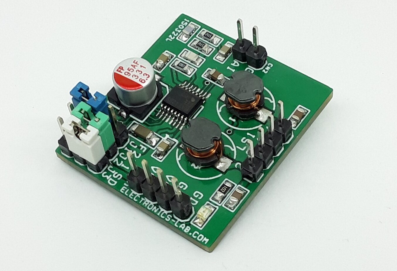
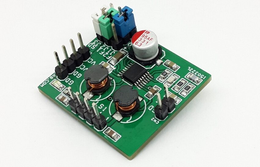
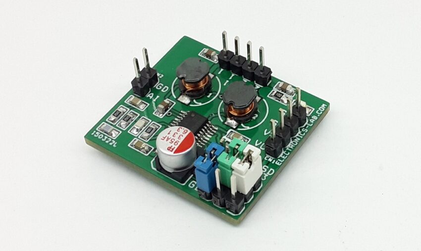
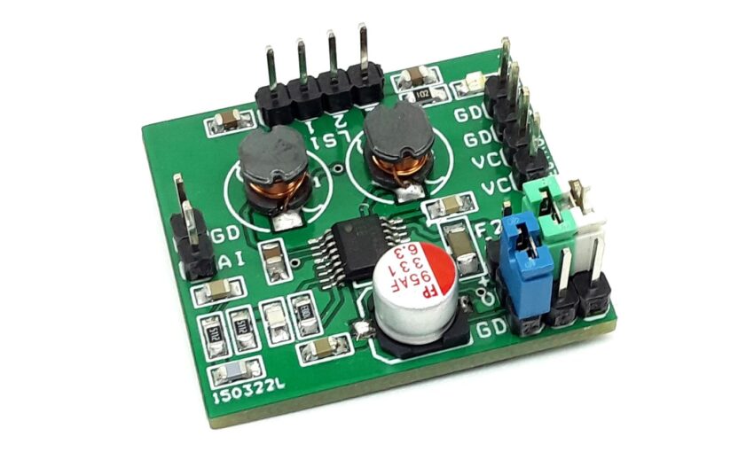
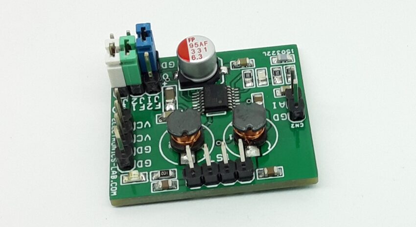
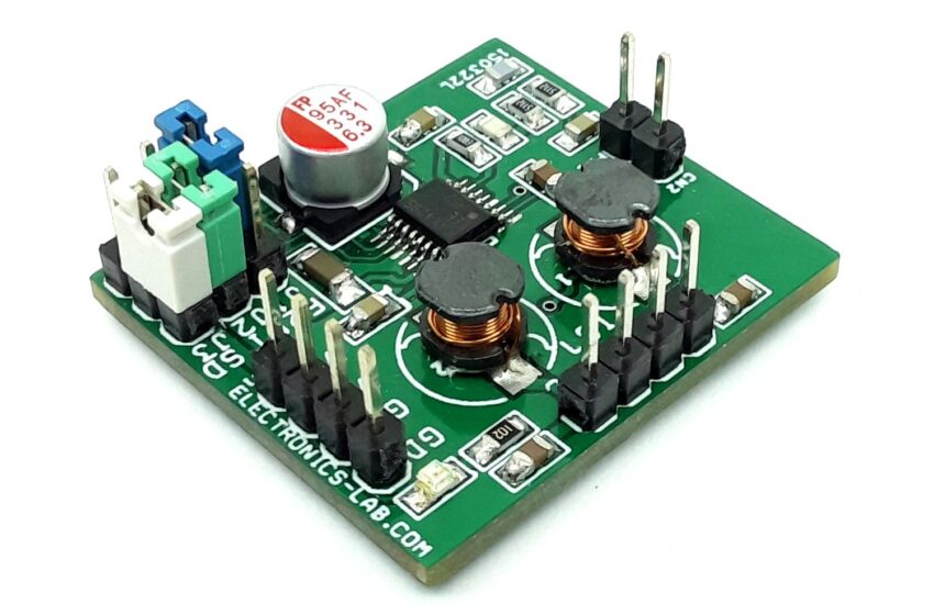
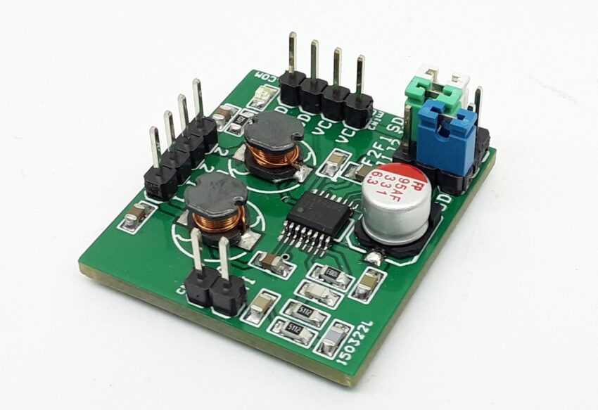
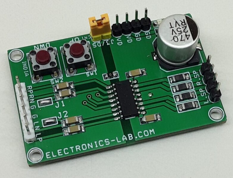
This is a compact size, mono, switch-mode (Class-D) audio power amplifier intended for multimedia and general-purpose high-power applications. It has greater than 87% efficiency and is capable of delivering 2W maximum continuous power to a 4Ω load. The project is designed to be driven by the line-out or headphone jack of a CD/MP3 player or to be directly connected to any audio source. The project includes header connectors for speakers, power supply, and audio input for quick connection. The project also has 3x jumpers for frequency selection and shutdown action. The project is built using the MAX4295 chip.
Undervoltage Lockout
At low supply voltages, the MOSFETs in the H-bridge may have inadequate gate drive thus dissipating excessive power. The Undervoltage lockout circuit prevents the device from operating at supply voltages below +2.2Vdc.
Low-Power Shutdown Mode (Jumper J3 for Shutdown)
The MAX4295 has a shutdown mode that reduces power consumption and extends battery life. Driving SHDN low disables the H-bridge, turns off the circuit, and places the MAX4295 in a low-power shutdown mode. Connect SHDN to VCC using jumper 3 for normal operation.
Frequency Selection (Jumper J1 and J2 For Frequency Selection)
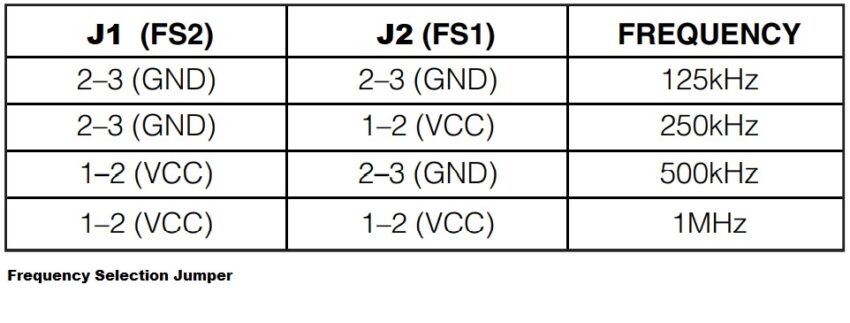
The MAX4295 has an internal logic-programmable oscillator controlled by FS1 and FS2 (see table below). The oscillator can be programmed to frequencies of 125kHz, 250kHz, 500kHz, and 1MHz. The working frequency should be chosen to best fit the user application. As a rule of thumb, choose fOSC to be 10x times the audio bandwidth. A lower switching frequency offers higher amplifier efficiency and lower THD but requires larger external filter components. A higher switching frequency reduces the size and cost of the filter components at the expense of THD and efficiency. In most applications, the optimal fOSC is 250kHz.
Connections and Other Details
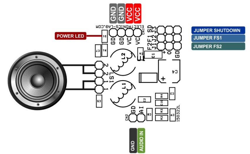
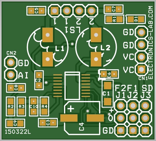
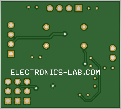
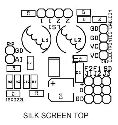
- CN1: Pin 1 and Pin 2 = VCC, Pin and Pin 4 = GND (VCC Supply 2.7V to 5.5V DC)
- LS1: Pin 1 and Pin 2 = Speaker 1, Pin 3 and Pin 4 = Speaker 2
- CN2: Pin 2 Audio Signal Input, Pin 1 GND
- Jumpers J1 and J2: Frequency select pins FS1 and FS2. See Table for the shunt positions.
- Jumper J3: Shutdown selection, GND= Shutdown
- D1: Power LED
Features
- Operating Power Supply +2.7V to +5.5V Input Range (1.5A)
- 2W Channel Output Power at 5V
- 7W/Channel Output Power at 3V
- 87% Efficiency (RL = 4Ω, POUT = 2W)
- Programmable PWM Oscillator Frequency Selection (125kHz, 250kHz, 500kHz, 1MHz)
- Low 0.4% THD+N (RL = 4Ω, fIN = 1kHz, fOSC = 250kHz)
- Low-Power Shutdown Mode
- 1A Current Limit and Thermal Protection
- Click fewer Transitions into and Out of Shutdown
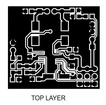
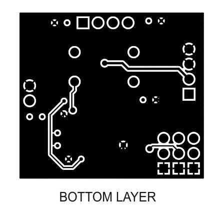
- PCB Dimensions 31.59 x 28.42 mm
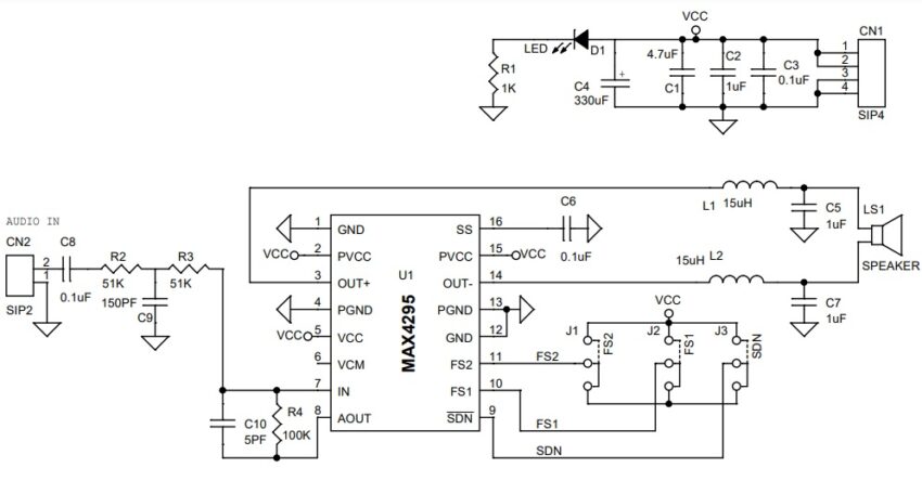
The MAX4295 switch-mode, Class D audio power amplifier is intended for portable multimedia and general-purpose audio applications. Linear amplifiers in the 1W to 2W output range are inefficient; they overheat when operated near rated output power levels. The efficiency of linear amplifiers is <50% when the output voltage is equal to 1/2 the supply. The MAX4295 Class D amplifier achieves efficiencies of 87% or greater and is capable of delivering up to 2W of continuous maximum power to a 4Ω load. The lost power is due mainly to the on-resistance of the power switches and ripple current in the output. In a Class D amplifier, a PWM controller converts the analog input to a variable pulse-width signal. The pulse width is proportional to the input voltage, ideally 0% for a 0V input signal and 100% for full-scale input voltages. A passive lowpass LC network filter the PWM output waveform to reconstruct the analog signal. The switching frequency is selected much higher than the maximum input frequencies so that intermodulation products are outside the input signal bandwidth. Higher switching frequencies also simplify the filtering requirements. The MAX4295 consists of an inverting input operational amplifier, a PWM ramp oscillator, a controller that converts the analog input to a variable pulse-width signal, and a MOSFET H-bridge power stage. The control signal is generated by the PWM comparator; its pulse width is proportional to the input voltage. Ideally the pulse width varies linearly between 0% for a 0V input signal and 100% for full-scale input voltages. This signal controls the H-bridge. The switches work in pairs to reverse the polarity of the signal in the load. Break-before-make switching of the H-bridge MOSFETs by the driver circuit keeps supply current glitches and crowbar current in the MOSFETs at a low level. The output swing of the H-bridge is a direct function of the supply voltage. Varying the oscillator swing in proportion to the supply voltage maintains constant gain with varying supply voltage. FS1 and FS2 program the oscillator to a frequency of 125kHz, 250kHz, 500kHz, and 1MHz. The sawtooth oscillator swings between GND and 0.6 x VCC. The input signal is typically AC-coupled to the internal input op-amp, whose gain can be controlled through external feedback components. The common-mode voltage of the input amplifier is 0.3 x VCC and is internally generated from the same resistive divider used to generate the 0.6 x VCC reference for the PWM oscillator.
Schematic
Parts List
| NO | QNTY. | REF. | DESC. | MANUFACTURER | SUPPLIER | PART NO |
|---|---|---|---|---|---|---|
| 1 | 1 | CN1 | 4 PIN MALE HEADER PITCH 2.54MM | WURTH | DIGIKEY | 732-5317-ND |
| 2 | 1 | CN2 | 2 PIN MALE HEADER PITCH 2.54MM | WURTH | DIGIKEY | 732-5315-ND |
| 3 | 1 | C1 | 4.7uF/10V SMD SIZE 0805 | YAGEO/MURATA | DIGIKEY | |
| 4 | 3 | C2,C5,C7 | 1uF/25V SMD SIZE 0805 | YAGEO/MURATA | DIGIKEY | |
| 5 | 3 | C3,C6,C8 | 0.1uF/25V SMD SIZE 0805 | YAGEO/MURATA | DIGIKEY | |
| 6 | 1 | C4 | 330uF/6.3V SMD ELECTROLYTIC | PANASONIC | DIGIKEY | 10-EEE-FKJ331XALCT-ND |
| 7 | 1 | C9 | 150PF/50V SMD SIZE 0805 | YAGEO/MURATA | DIGIKEY | |
| 8 | 1 | C10 | 5PF/50V SMD SIZE 0805 | YAGEO/MURATA | DIGIKEY | |
| 9 | 1 | D1 | LED RED SMD SIZE 0805 | LITE ON INC | DIGIKEY | 160-1427-1-ND |
| 10 | 1 | J1 | 2 PIN MALE HEADER PITCH 2.54MM | WURTH | DIGIKEY | 732-5315-ND |
| 11 | 1 | J2 | 2 PIN MALE HEADER PITCH 2.54MM | WURTH | DIGIKEY | 732-5315-ND |
| 12 | 1 | J3 | 2 PIN MALE HEADER PITCH 2.54MM | WURTH | DIGIKEY | 732-5315-ND |
| 13 | 1 | LS1 | 2 PIN MALE HEADER PITCH 2.54MM | WURTH | DIGIKEY | 732-5315-ND |
| 14 | 2 | L1,L2 | 15uH | TAIYO UDEN | 587-2630-1-ND | |
| 15 | 1 | R1 | 1K 5% SMD SIZE 0805 | YAGEO/MURATA | DIGIKEY | |
| 16 | 2 | R2,R3 | 51K 1% SMD SIZE 0805 | YAGEO/MURATA | DIGIKEY | |
| 17 | 1 | R4 | 100K 5% SMD SIZE 0805 | YAGEO/MURATA | DIGIKEY | |
| 18 | 1 | U1 | MAX4295 | ANALOG DEVICES | DIGIKEY | MAX4295EEE+-ND |
| 19 | 3 | J1-S | SHUNT FOR J1, J2, J3 | SULLINS CONCT | DIGIKEY | S9001-ND |
Connections
Frequency Table


