PC Hardware Monitor with Nokia 5110 Display and Arduino
- Emmanuel Odunlade
- https://twitter.com/emmaodunlade
- emmaodunlade@gmail.com
- 8.491 Views
- medium
- Tested
Either for benchmarking purposes or as external telemetry to help you stay within the acceptable range for your computer power, super users usually have the desire to have a way of knowing what the performance numbers of your PC are. For today’s tutorial, we will build a PC Hardware monitor which is capable of obtaining several performance-related parameters from your computer and displaying them on a Nokia 5110 LCD display.
Our PC Hardware monitor tutorial is based on the Arduino Nano microcontroller and a Nokia 5110 LCD Display. We have extensively used both of the components in past tutorials, especially the Nokia 5110 LCD Display for which we have done tutorials on displaying custom graphics, and several more tutorials on creating a custom menu on the display etc.
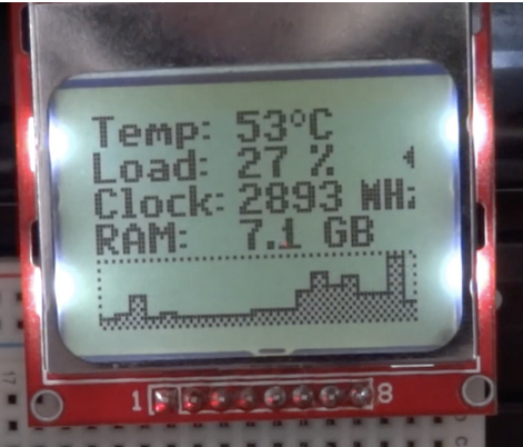
The principle of operation of today’s project is based on the “Grant Snatts” Hardware Serial Monitor project, which in turn, is based on the SerialSender utility which uses the open-source OpenHardwareMonitorLib.dll to sniff the sensors of the dedicated GPUs, graphic Cards, CPU and motherboards of most modern personal computers whilst, also pooling windows hardware stats. This stats and data are then obtained by the Arduino over the serial port and displayed on the Nokia 5110 LCD display. To do a better than other versions of the project out there, rather than just displaying the data, we will plot performance graphs to show information the CPU Load and the CPU Clock.
At the end of today’s tutorial, you would know things like graph plotting etc on the Nokia 5110 as well as interacting with the PC directly using the Arduino.
Required Components
The following components are required to build this project.
- Arduino Nano or Arduino Pro Mini with USB to serial adapter
- Nokia 5110 LCD
- Jumper Wires
- Breadboard
These components can be bought from any electronic components store online.
Schematics
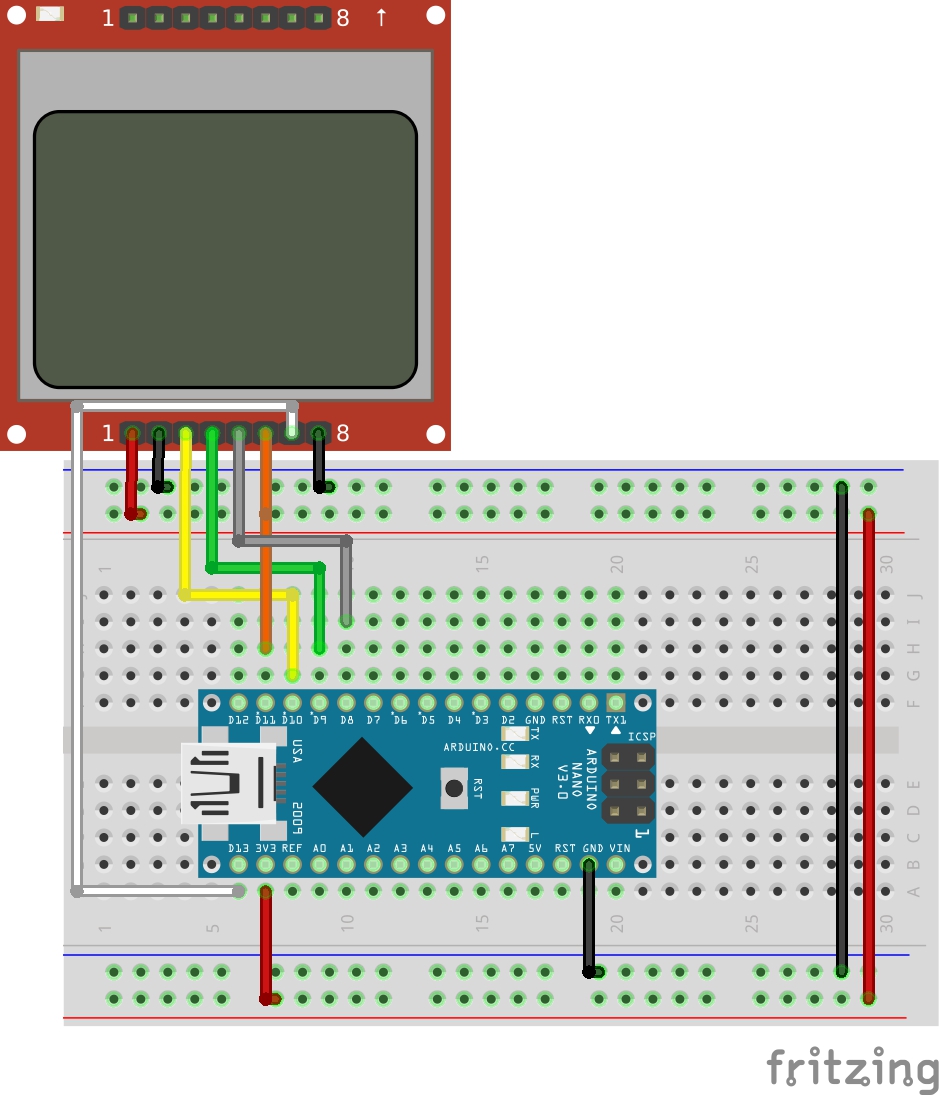
The schematics for this project is simple and should be familiar if you have been following several of our tutorials. Since the project is made up of just two main components, all we need to do is connect the Nokia 5110 LCD Display to the Arduino as shown in the schematics below;
To further make the connection easy to follow, a pin to pin connection between the Arduino and Nokia 5110 LCD display is described below.
Nokia 5110 – Arduino
VCC - 3.3V
GND - GND
DC - D8
RST - D9
CS/CE - D10
MOSI/DIN - D11
SCK/CLK - D13
LIGHT  - GND
Go over the connections once more to ensure everything is as it should be.
Code
The code for this project is quite straight forward. We obtain PC performance information via serial communication from the hardware monitor utility and display on the LCD as a graph and in raw data form.
To achieve this, we use N5110_SPI.h minimalistic Arduino library by cbm80amiga. The library uses a very small amount of MCU resources and contains methods that reduce the amount of code you need to write to display data on the Nokia 5110 LCD.
As usual, I will be doing a brief run through the code to explain some of its technical parts.
We start the sketch by including the libraries that we will use. In addition to the N5110_SPI library, we will use two fonts libraries; c64enh_font.h and small5x7bold_font.h They are attached under the download section.
#include "N5110_SPI.h"
// from PropFonts library
#include "c64enh_font.h"
#include "small5x7bold_font.h"
Next, we create an instance of the N5110_SPI library with the Arduino pins to which its, RST, CS, and DC pins are connected as arguments.
// define USESPI in above header for HW SPI version
N5110_SPI lcd(9,10,8); // RST,CS,DC

#if USESPI==1
#include <SPI.h>
#endif
We then choose if we want to display the load graph or clock graph.
// comment out for load graph
#define CLOCK_GRAPH
Next, create other variables that will be used in the code to store information retrieved from the PC among others.
String inputString = "";
char buf[30];
String cpuLoadString;
String cpuTempString;
String cpuClockString;
String ramString;
int cpuLoad=0;
int cpuClock=0;
int inp=0;
#define MIN_CLOCK 400
#define MAX_CLOCK 2900
#define NUM_VAL (21)
int valTab[NUM_VAL];
int i,ght=16;
int x=0;
Next, We write the void setup function. We start the function by initializing the serial monitor which we will use for debug purposes. Next, we initialize the LCD, set the font and display the string “Connecting” at the center of the screen.
void setup()
{
  Serial.begin(9600);
  inputString.reserve(200);

  lcd.init();
  lcd.clrScr();
  lcd.setFont(c64enh);
  lcd.printStr(ALIGN_CENTER, 2, "Connecting ...");
}
With that done, we create the function readSerial. This function does 80% of the work involved in this project. The function picks up the data sent by the utility over serial and extracts the CPU Clock, the RAM usage, CPU temperature and CPU load information from the serial data stream.
int readSerial()
{
  while (Serial.available()) {
    char ch = (char)Serial.read();
    inputString += ch;
    if(ch == '|') {  // full info chunk received
      int st,en;
      st = inputString.indexOf("CHC");  // CPU clock: "CHC1768"
      if(st>=0) {
        en = inputString.indexOf("|", st);
        cpuClockString = inputString.substring(st+3, en);
        cpuClock = cpuClockString.toInt();
        inp=3;
      } else {

        st = inputString.indexOf("R");  // used RAM: "R6.9"
        if(st>=0) {
          en = inputString.indexOf("|", st);
          ramString = inputString.substring(st+1 , en-1);
          st = ramString.indexOf(",");
          if(st>=0) ramString.setCharAt(st,'.');
          inp=2;
        }

        int cpuTempStart = inputString.indexOf("C"); // CPU temperature: "C52"
        int cpuLoadStart = inputString.indexOf("c"); // CPU load: "c18%"
        if(cpuLoadStart>=0 && cpuTempStart>=0) {
          en = inputString.indexOf("|");
          cpuTempString = inputString.substring(cpuTempStart+1, cpuLoadStart);
          cpuLoadString = inputString.substring(cpuLoadStart+1, en-1);
          cpuLoad = cpuLoadString.toInt();
          inp=1;
        }
      }
      inputString = "";
      return 1;
    }
  }
  return 0;
}
Next, is the void loop() function. The void loop function checks to see if the serial data is available by calling the readserial function. If data is available from the PC, it then displays the extracted data from the readserial() function on the LCD Display, while also using the LCD.fillWin() and drawGraphBar() function to plot the graph.
void loop()
{
  //readSerial();
  if(readSerial())
  {
    int xs=38;
    lcd.setFont(c64enh);
    lcd.printStr(0, 0, "Temp: ");
    x=lcd.printStr(xs, 0, (char*)cpuTempString.c_str());
    lcd.printStr(x, 0, "'C  ");
    lcd.printStr(0, 1, "Load: ");
    snprintf(buf,20,"%d %",cpuLoad);
    x=lcd.printStr(xs, 1, buf);
    lcd.printStr(x, 1, "%  ");
    lcd.printStr(0, 3, "RAM: ");
    x=lcd.printStr(xs, 3, (char*)ramString.c_str());
    lcd.printStr(x, 3, " GB  ");
    lcd.printStr(0, 2, "Clock: ");
    x=lcd.printStr(xs, 2, (char*)cpuClockString.c_str());
    lcd.setFont(Small5x7PLBold);
    lcd.printStr(x, 2, " MHz    ");
#ifdef CLOCK_GRAPH
    i = 2;
#else
    i = 1;
#endif
    lcd.fillWin(83,i,1,1,B00111110);
    lcd.fillWin(82,i,1,1,B00011100);
    lcd.fillWin(81,i,1,1,B00001000);

    if(inp==3) addVal();
    clrBuf();
    drawGraphBar();
    lcd.drawBuf(scr,0,4,scrWd,scrHt);
  }
  if(inp>=3) { delay(1000); inp=0; }
}
The complete code for the project is available below and under the download section. It contains all the other functions that were used and is well commented so it should be easy to follow irrespective of your programming experience.
#include "N5110_SPI.h"
// from PropFonts library
#include "c64enh_font.h"
#include "small5x7bold_font.h"

// define USESPI in above header for HW SPI version
N5110_SPI lcd(9,10,8); // RST,CS,DC

#if USESPI==1
#include <SPI.h>
#endif


// comment out for load graph
#define CLOCK_GRAPH

String inputString = "";
char buf[30];
String cpuLoadString;
String cpuTempString;
String cpuClockString;
String ramString;
int cpuLoad=0;
int cpuClock=0;
int inp=0;
#define MIN_CLOCK 400
#define MAX_CLOCK 2900
#define NUM_VAL (21)
int valTab[NUM_VAL];
int i,ght=16;
int x=0;


void setup()
{
  Serial.begin(9600);
  inputString.reserve(200);

  lcd.init();
  lcd.clrScr();
  lcd.setFont(c64enh);
  lcd.printStr(ALIGN_CENTER, 2, "Connecting ...");
}

int readSerial()
{
  while (Serial.available()) {
    char ch = (char)Serial.read();
    inputString += ch;
    if(ch == '|') {  // full info chunk received
      int st,en;
      st = inputString.indexOf("CHC");  // CPU clock: "CHC1768"
      if(st>=0) {
        en = inputString.indexOf("|", st);
        cpuClockString = inputString.substring(st+3, en);
        cpuClock = cpuClockString.toInt();
        inp=3;
      } else {

        st = inputString.indexOf("R");  // used RAM: "R6.9"
        if(st>=0) {
          en = inputString.indexOf("|", st);
          ramString = inputString.substring(st+1 , en-1);
          st = ramString.indexOf(",");
          if(st>=0) ramString.setCharAt(st,'.');
          inp=2;
        }

        int cpuTempStart = inputString.indexOf("C"); // CPU temperature: "C52"
        int cpuLoadStart = inputString.indexOf("c"); // CPU load: "c18%"
        if(cpuLoadStart>=0 && cpuTempStart>=0) {
          en = inputString.indexOf("|");
          cpuTempString = inputString.substring(cpuTempStart+1, cpuLoadStart);
          cpuLoadString = inputString.substring(cpuLoadStart+1, en-1);
          cpuLoad = cpuLoadString.toInt();
          inp=1;
        }
      }
      inputString = "";
      return 1;
    }
  }
  return 0;
}


void addVal()
{
  for(i=0;i<NUM_VAL-1;i++) valTab[i]=valTab[i+1];
#ifdef CLOCK_GRAPH
  if(cpuClock<400) cpuClock=400;
  if(cpuClock>2900) cpuClock=2900;
  valTab[NUM_VAL-1] = (long)(cpuClock-MIN_CLOCK)*ght/(MAX_CLOCK-MIN_CLOCK);
#else
  valTab[NUM_VAL-1] = cpuLoad*ght/100;
#endif
}

// --------------------------------------------------------------------------
byte scr[84*2];  // frame buffer
byte scrWd = 84;
byte scrHt = 2;

void clrBuf()
{
  for(int i=0;i<scrWd*scrHt;i++) scr[i]=0;
}

void drawPixel(int16_t x, int16_t y, uint16_t color)
{
  if((x < 0) || (x >= scrWd) || (y < 0) || (y >= scrHt*8)) return;
  switch (color) {
    case 1: scr[x+(y/8)*scrWd] |=  (1 << (y&7)); break;
    case 0: scr[x+(y/8)*scrWd] &= ~(1 << (y&7)); break;
    case 2: scr[x+(y/8)*scrWd] ^=  (1 << (y&7)); break;
  }
}

void drawLineH(uint8_t x0, uint8_t x1, uint8_t y, uint8_t step)
{
  if(step>1) { if(((x0&1)==1 && (y&1)==0) || ((x0&1)==0 && (y&1)==1)) x0++; }
  if(x1>x0) for(uint8_t x=x0; x<=x1; x+=step) drawPixel(x,y,1);
  else      for(uint8_t x=x1; x<=x0; x+=step) drawPixel(x,y,1);
}

void drawLineV(int x, int y0, int y1, int step)
{
  if(step>1) { if(((x&1)==1 && (y0&1)==0) || ((x&1)==0 && (y0&1)==1)) y0++; }
  if(y1>y0)for(int y=y0; y<=y1; y+=step) drawPixel(x,y,1);
  else     for(int y=y1; y<=y0; y+=step) drawPixel(x,y,1);
}

// --------------------------------------------------------------------------

void drawGraphBar()
{
  drawLineH(0,83,0,2);
  drawLineH(0,83,15,2);
  drawLineV(0,0,15,2);
  drawLineV(83,0,15,2);
  for(i=0;i<NUM_VAL;i++) {
    drawLineH(i*4,(i+1)*4-1,15-valTab[i],1);
    drawLineV(i*4+0,15-valTab[i],15,2);
    drawLineV(i*4+1,15-valTab[i],15,2);
    drawLineV(i*4+2,15-valTab[i],15,2);
    drawLineV(i*4+3,15-valTab[i],15,2);
    if(i>0) drawLineV(i*4,15-valTab[i-1],15-valTab[i],1);
  }
}

void loop()
{
  //readSerial();
  if(readSerial())
  {
    int xs=38;
    lcd.setFont(c64enh);
    lcd.printStr(0, 0, "Temp: ");
    x=lcd.printStr(xs, 0, (char*)cpuTempString.c_str());
    lcd.printStr(x, 0, "'C  ");
    lcd.printStr(0, 1, "Load: ");
    snprintf(buf,20,"%d %",cpuLoad);
    x=lcd.printStr(xs, 1, buf);
    lcd.printStr(x, 1, "%  ");
    lcd.printStr(0, 3, "RAM: ");
    x=lcd.printStr(xs, 3, (char*)ramString.c_str());
    lcd.printStr(x, 3, " GB  ");
    lcd.printStr(0, 2, "Clock: ");
    x=lcd.printStr(xs, 2, (char*)cpuClockString.c_str());
    lcd.setFont(Small5x7PLBold);
    lcd.printStr(x, 2, " MHz    ");
#ifdef CLOCK_GRAPH
    i = 2;
#else
    i = 1;
#endif
    lcd.fillWin(83,i,1,1,B00111110);
    lcd.fillWin(82,i,1,1,B00011100);
    lcd.fillWin(81,i,1,1,B00001000);

    if(inp==3) addVal();
    clrBuf();
    drawGraphBar();
    lcd.drawBuf(scr,0,4,scrWd,scrHt);
  }
  if(inp>=3) { delay(1000); inp=0; }
}
Demo
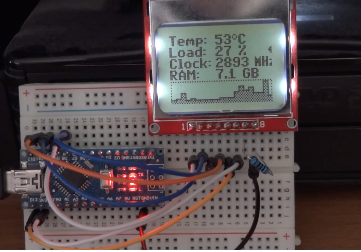
With the code complete and the hardware connected as described under the schematics, connect the Arduino board to the computer and upload the code. Launch the hardware monitor software (attached under the download section) as an administrator and select the right com port to match the port on which your Arduino board is connected.
With this done, you should see the screen come up with PC performance information being displayed as shown in the image below.
To take things forward and improve on the project, how about we make things wireless?
That’s it for this tutorial, thanks for reading along. Feel free to reach out to me via the comment section with any question you might have about it.
The project is based on the work of cbm80amiga, you can watch a video of the device in action on youtube.


