400V – 5A Power Supply For Brushless Motor Drivers
- Rajkumar Sharma
- 19.946 Views
- medium
- Tested
- SKU: EL66116
- Quote Now
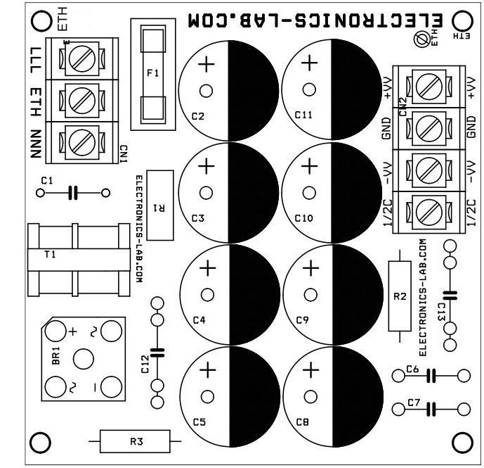
Although the power supply design is specific to the Brushless Servo Drivers mainly for IPM Modules, the concepts and circuit design may be used for any power supply that requires high voltage output up to 400V DC and 5 Amps. The power supply is an unregulated design with an option to allow connection to either 120V or 230V mains and also it can work with lower voltage for audio amplifiers by increasing capacitor value. The design uses a fully integrated bridge rectifier, and multiple bus capacitors for low ripple, noise suppression, and provides high current reservoirs. Additionally, the dc supply line has bleeder resistor R2 and R3 to drain the large reservoir capacitors PCB, mounted fuse holder provided for short circuit and over current protections, low ohm NTC used for inrush current at power start-up, C1, C12, TX protects against turn on/off spikes and EMI noise reduction. This power supply can be used to drive Tesla Coils, Induction heaters, DC Motor drivers, Brushless DC motor driver.
This power supply is ideal to be used with High Voltage-Current Half Bridge Driver Using IR2153 & IGBT
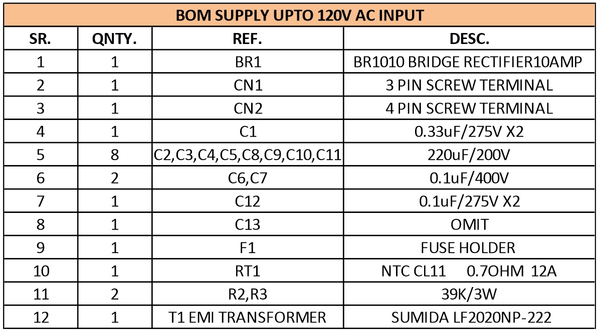
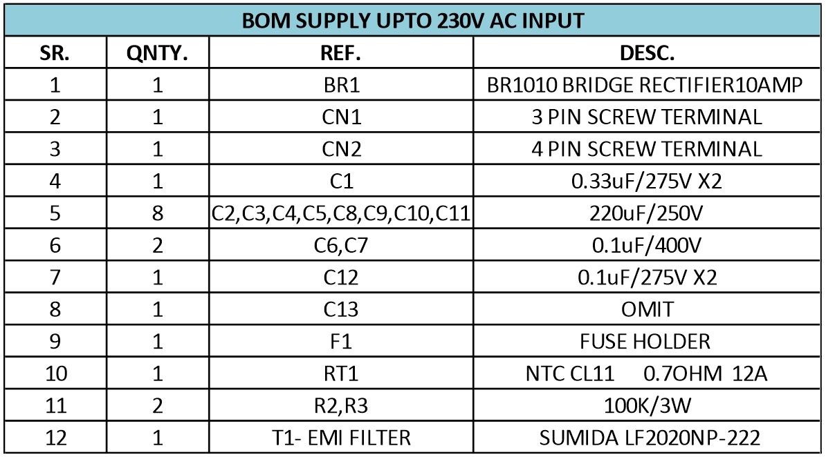
Note: Two BOM provided for supply up to 120V AC and BOM 2 for supply input up to 230V AC
T1 is a common mode choke 2.2 mH/ 1.3 A with 0.24 Ohms DC resistance. Refer to mouser #851-LF2020NP-222
Features
- AC Supply input up to 120V AC or 230V AC, depending on R2,R3 choice (see BOM)
- Maximum DC Output 400V DC and 5Amps.
- 230V AC Input possible with few components value alteration
- DC Supply Output will depend on the input supply
- Fuse for Short circuit and over current protection
- Fuse as per your application requirement Maximum 5Amps Fuse
- NTC provided for inrush current
- DC Bus has a bleeding resistor
Schematic
Parts List
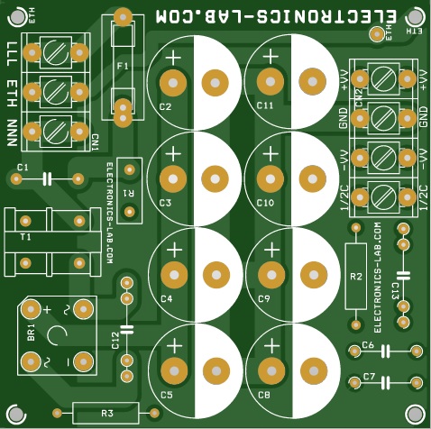
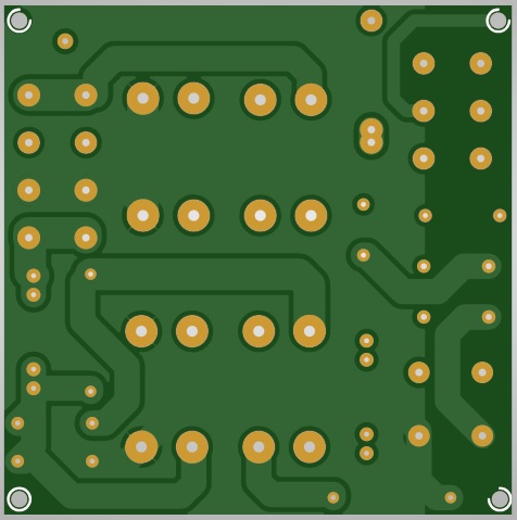
Gerber View
Photos


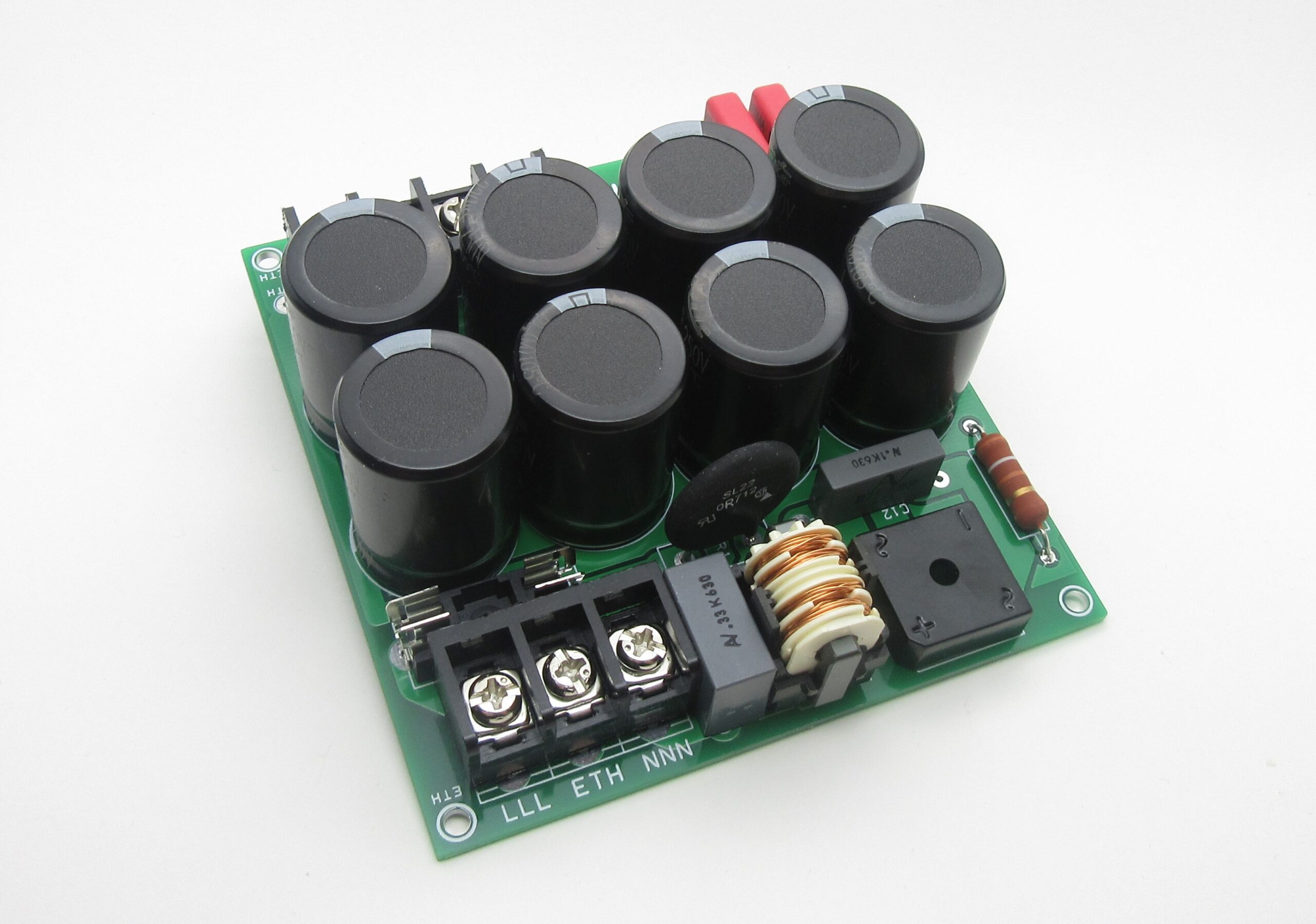

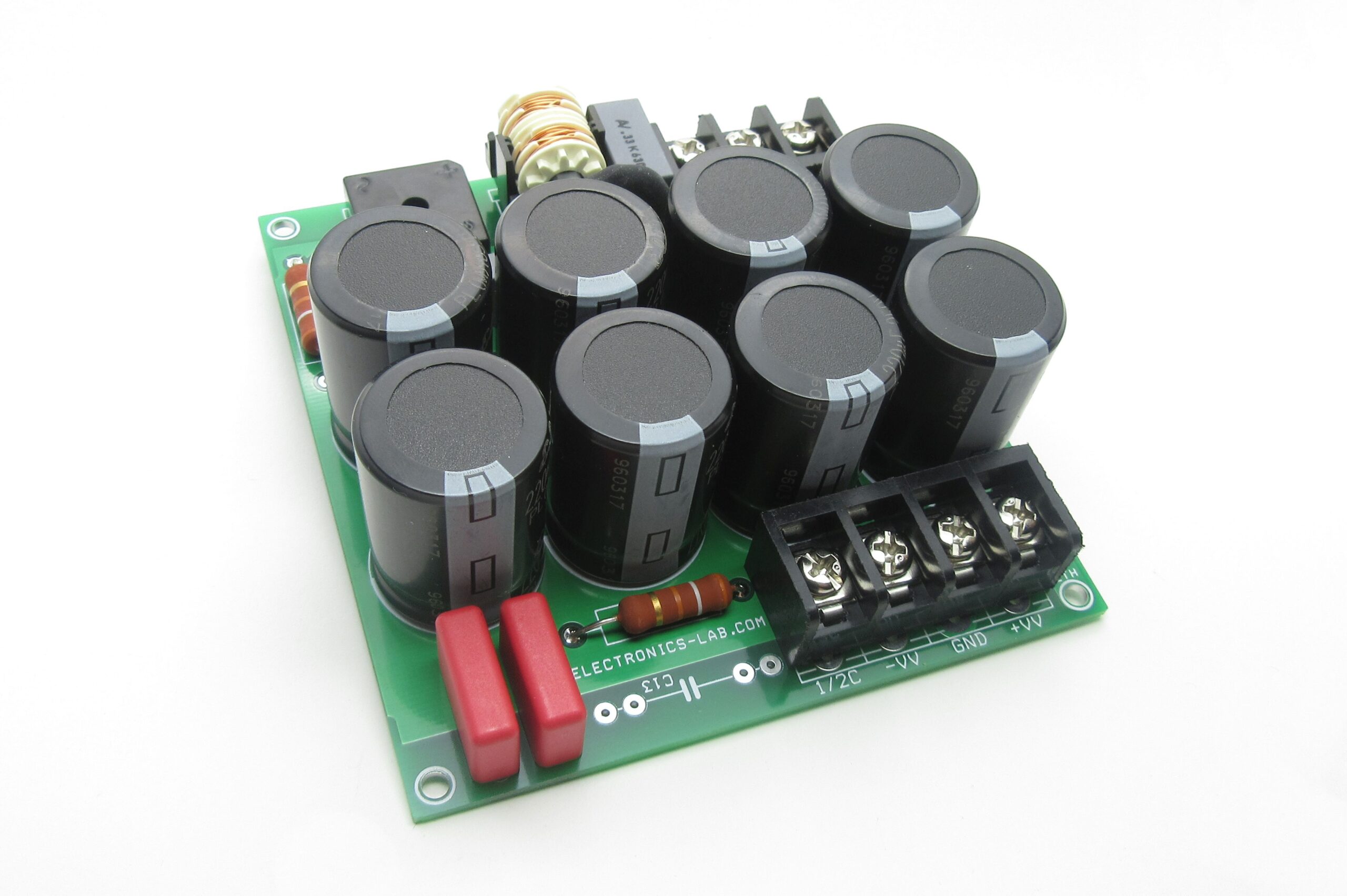
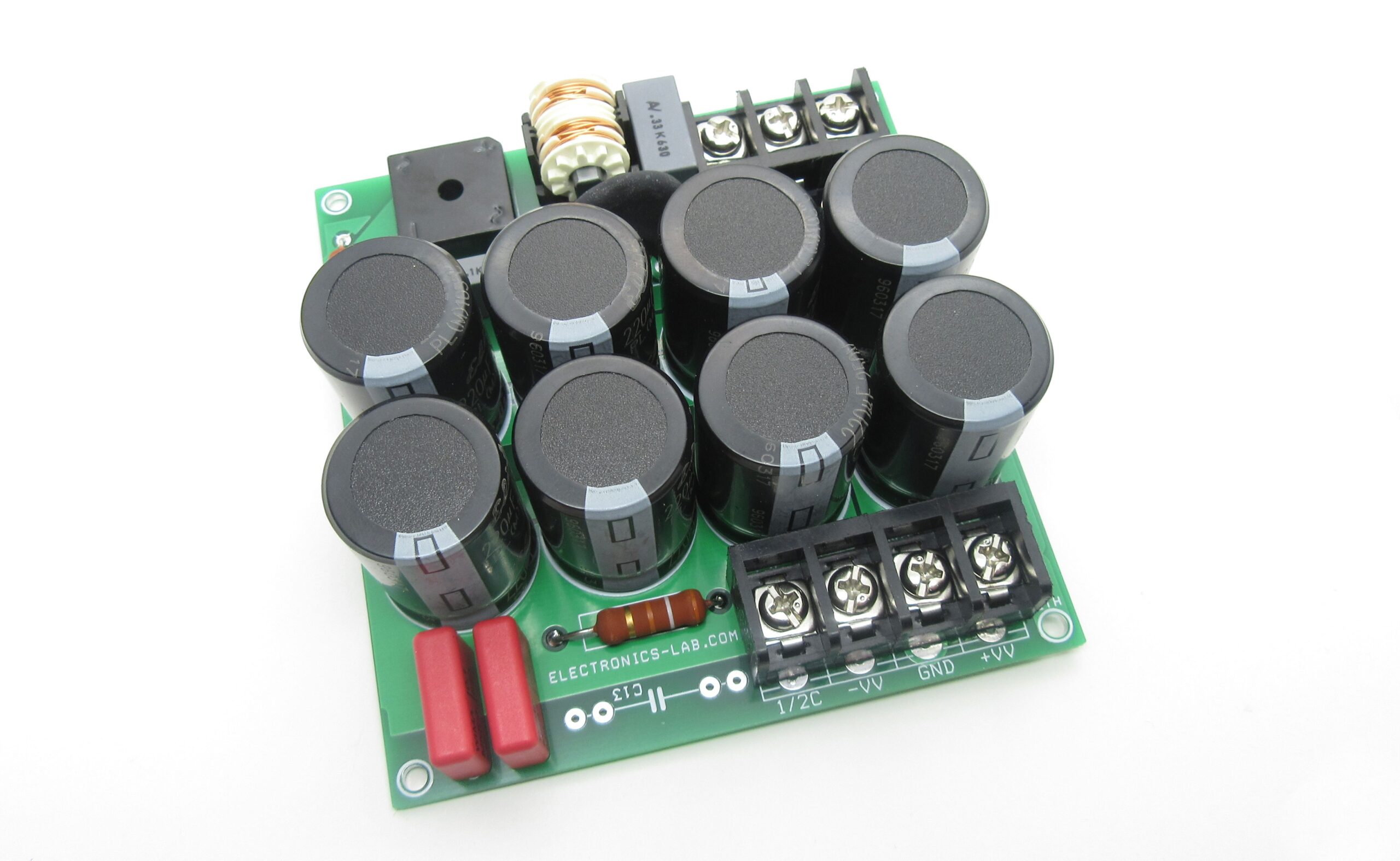
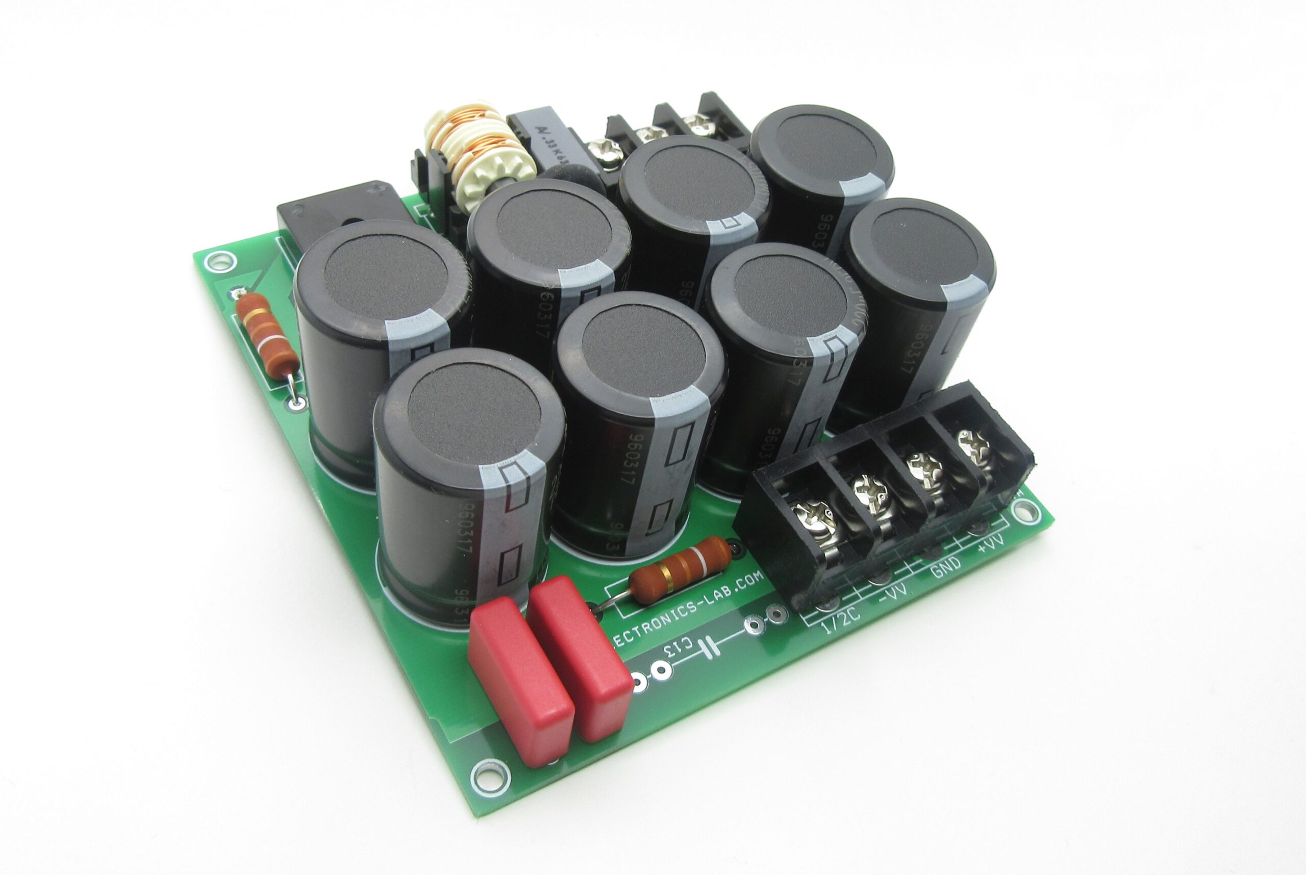
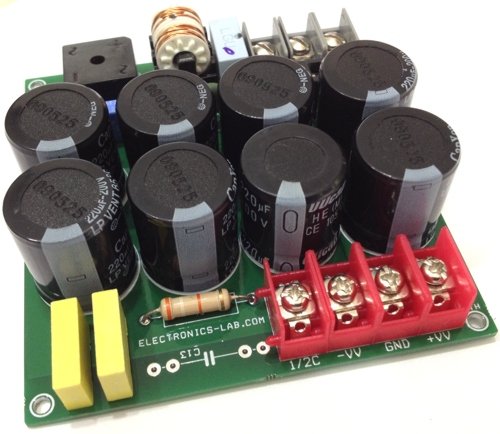
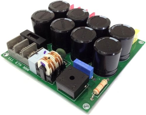
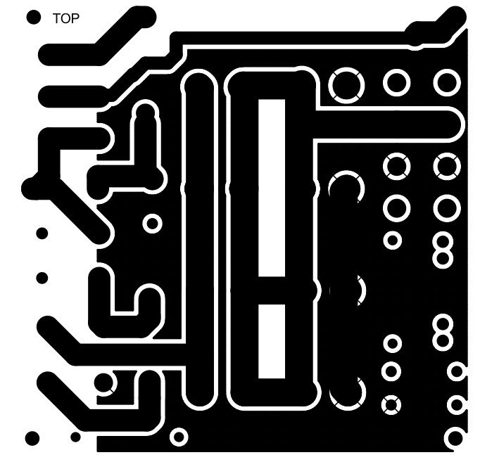
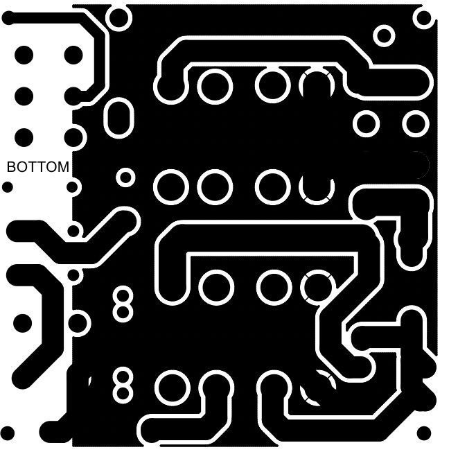


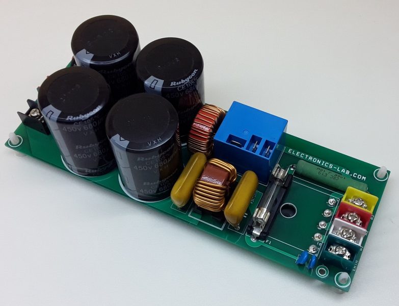
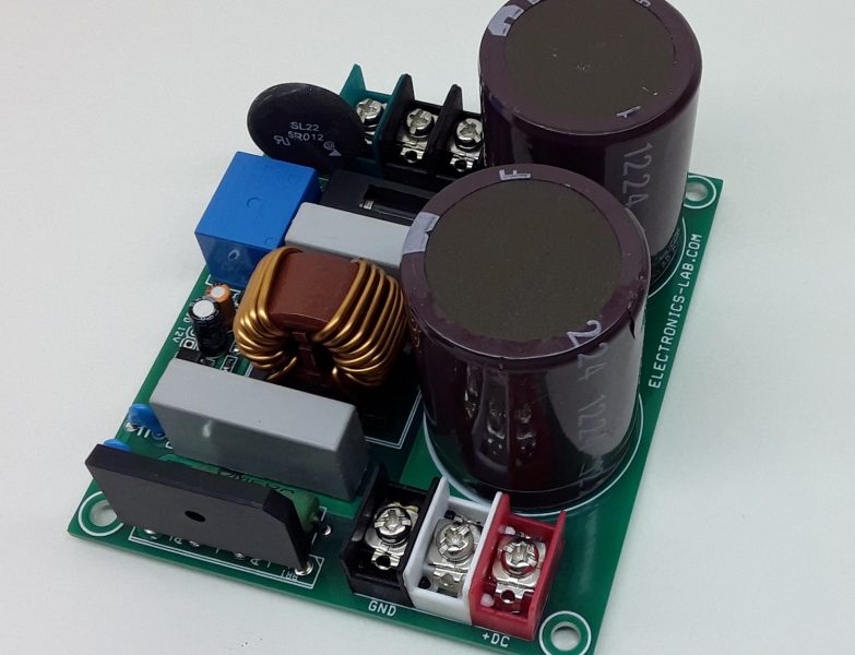
Could you indicate a part number or specs for T1? Does T1 provide any isolation between input and output?
I uploaded the datasheet of this transformer here: https://electronics-lab.com/community/index.php?/topic/41811-part-number-of-t1-for-400v-%E2%80%93-5a-power-supply-for-brushless-motor-drivers/
This is used to reduce noise and doesn’t provide isolation between the input and output.
where to buy it?
Sorry, we don’t sell this board yet.
You can also use this part for T1: https://gr.mouser.com/ProductDetail/851-LF2020NP-222
400 v dc 5 Amp brushless motor drive ,i need one only for test on direct motor drive (washing machine motor)sensorless ,do you sell on ebay?
We are sorry, we don’t sell kits or assembled boards. If you need one piece you will have to build it your own.
can i use for 3 phase motor control?
This is just a 400V/5A power supply and can be used on a Motor Control Board that requires such voltages.
hello,
May i know what difference Gnd and -V on circuit. Where to connect gnd actually in circuit.Thanks
GND is the reference (0V) for the positive +V and negative -V voltages produced.
please can you explain the function of C13 and why there is a Ground-Terminal on the output? because i think you cannot get energy between V+ and GND or V- and GND.
This capacitor required to protect the IGBT/MOSFET when used in Tesla coil projects. The capacitor is replaced by inductor when its used in induction heating applications. You can surely get energy between V+ or V- and GND. Please note this is the system GND and not mains EARTH.
Is this board for sale?
How many pieces do you need?
Have you got an MOQ?
Yes, as we don’t have these in stock and usually don’t sell kits or assembled products, we have to manufacture them for you. So our MOQ is 25 pieces.
Thank you Mike,
So how much would 25 boards be and 25 kits?
Thanks,
Graeme
I’ve send you a quote on your email. Thanks
CAN THIS CIRCUIT USED FOR TREADMILL MOTOR?
This is a general question. We can’t say if we don’t know the motor type and specifications.
Good Evening,
I have purchased the BOM for this project and tested the output. I had received 170VDC at OUTPUT of V+and V-. This voltage, i calculated was from Vrms= 120VAC. and Vpeak=1.4*Vrms = 170 VDC. I know the description says output depends on input. but if i put in 230VAC into the circuit, i am predicting i will get around 330VDC. Is there anyway to receive 400V 5 AMP from 120VAC input supply. or does it need to be bumped up to get this voltage?
I tested the V out with no load, and a voltmeter
Thanks,
Kevin
Good Evening, I have bought the supplies and made the PCB for this project, but i am only getting 170 VDC out. I am supplying 120 VAC and this makes sense as the Vrms =120 VAC, and 1.41* Vrms=Vpeak=170VDC. THis was at no load. (Tested with multimeter). How do i achieve 400V output voltage? Even if i made the 230AC supply circuit, the output would be 324.4 VDC.
Please let me know what i can do to get it to 400 V. I am looking to power multiple motors that draw high amperage.
thank you.
As you can see above, 400V is the maximum output voltage that the circuit can handle. So for higher DC output you will need a higher AC input.
Hey mike, so how would I achieve 400V max, I’d the maximum input supply you have is 220V. 220Vx1.4= 308 VDC. This is not near 400V. You would need to supply more than 220 V. And that would mean that the board wouldnt be able to take that power input.
Is there anyway to get 400V put of the 120VAC board?
Thanks.
No, there is no such way. This board does rectification and filtering of AC input signal and not stepping it up.
Hello is it possible to have 5 pcs for 230Vac input? how much time does it take to get it?
Check your email for my answer to this.
What type of terminal to use. Do they come with two solder PINs for each terminal or double up of solder pads on PCB as an option.
You can use 10mm pitch block terminals like these: https://www.aliexpress.com/item/1005003021965094.html
Thanks, i found some, all parts gathered ready to assemble 🙂
ok, take precautions for the lethal voltages of this board, and feel free to share your feedback.