Programmable Day-Night Light Controller based on ATmega8
- Dilshan R Jayakody
- http://jayakody2000lk.blogspot.com
- jayakody2000lk@gmail.com
- 4.852 Views
- medium
- Tested
A low-cost, easy-to-build, high-power LED controller with a built-in programmable timer.
The main objective of this project is to design a maintenance free and low-cost light which automatically turns on and off at the predetermined time of the day.
This kind of light helps to reduce power waste and save energy. In these days people have a habit to turn on at least one light of there residence if they are going out of home for a couple of days. Then lights start to blazing all day and night and waste lots of energy. If we can use this programmable light, then we can configure it to turn on every night and turn off at the next day by without any human involvement.
The core component of this programmable light is ATmega8 low power CMOS microcontroller. The main reason to select this microcontroller is it’s lower cost and higher availability. Except for the above two reasons this microcontroller also bundled with a rich set of peripherals which including 23 GPIOs, 3 independent timers, Two-wire serial interface, EEPROM, etc.
Apart from ATmega8 microcontroller, this system uses DS1307 real time clock to maintain system time. Like ATmega8, DS1307 is also a very popular RTC in the market.
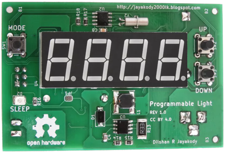
This controller is designed to work with a 24V DC power supply. The main reason to select 24V is that most of the medium power LED modules in the market are designed to work with that voltage. During my search all the medium power LED modules which I found are designed to work with 20V – 28V range. Out of those LED modules, the majority of modules are rated for 24V input.
For this circuit, the recommended power supply is 24V 1.5 A portable switch mode power supply. Except for the LED driver stage the all other parts of this light controller is designed to work with 5V. MC34063 DC-to-DC converter is used to supply 5V to those components.
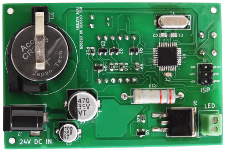
To reduce the size I design this system using surface-mounted components, but this system can also build using through-hole type components. At the prototype stages, I build this system entirely on a breadboard using through-hole type parts.
To build 7W light, I used LED lamp parts available in the market which including Warm white 7W LED panel, aluminum lamp shell (heatsink) and diffusing cap (lamp cover).
Construction
As mentioned previously this programmable light can build in many ways which including using PCB, Veroboard, breadboard, etc. The most favored way to construct this system is using a PCB.
The PCB design which I provide is based on 2 layers and because of that, it’s advised to build this PCB using some PCB fabrication service.

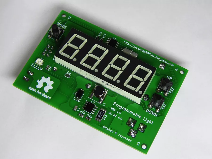
After fabricating PCB, you can start soldering the components into it. At first, try to solder SMD ICs. After soldering all 3 ICs next start with small SMD components such as resistors, capacitors and SOT-23 transistors. I highly suggest installing seven segment display, DC jack base, battery clips and terminals header at the last stages of the soldering.
Upload firmware into the system
Once all the components are assembled the next task is to feed firmware into the microcontroller. To upload the firmware the most recommended method is to use AVR in-circuit programming (ISP) compliant adapter.
This system is designed to work with standard 6-pin AVR ISP interface and there are plenty of programmers are available for this interface.
During my prototype assembly, I used a USBasp programmer to flash the microcontroller with firmware.
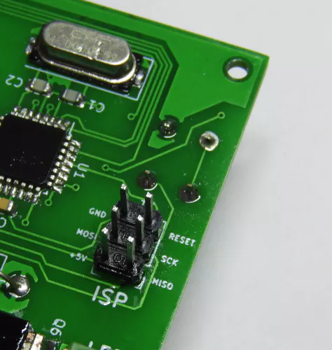
During the firmware upload process pays extra attention to ATMega8 fuse settings. To get intended results low-fuse byte should set to 0xEF and high-fuse byte should set to 0xD9. For more details refer project documentation at the GitHub.
While using ISP make sure to disconnect the 24V power supply from the system.
LED module
After uploading firmware, the only remaining task is to connect the LED module into the controller.
Before soldering 7W LED module, fix it to the provided heatsink. To improve thermal transfer make sure to apply thermal grease between the LED module and heatsink.
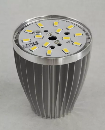
While LED lighting for long hours its temperature increase up to 70°C – 80°C. Because of this, make sure to take necessary action(s) to isolate the LED wire line with temperature. To overcome this, in prototype build I drive this wire through a high-temperature resistant Basalt sleeve.
Using the light controller
At the first power up light controller starts with default settings. To modify those settings hold down “MODE” button for a few seconds and then it opens the System menu.
System menu consists of 4 options such as “SYS”, “ON”, “OFF” and “—”. You can modify the value associated with each option by pressing the “MODE” button. In System menu press “UP” or “DOWN” buttons to navigate over the available modes.
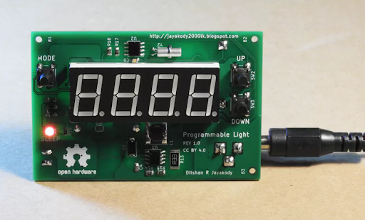
In “SYS” mode user can change the system time. Likewise in “ON” and “OFF” modes, the user can set the light on and off times respectively.
To leave the System menu, press the “MODE” button in “—” mode.
The light controller firmware is designed to switch to the idle state if the user is not involved with the system for a long period of time. In the idle state, seven segment display of the light controller is not active. In most occasions SLEEP indicator also got activate in an idle state.
The all options available in the light controller are explained with more details in the user guide available at the GitHub.
Project files and source code
The light controller project which described in this article is a certified open hardware project. All the design files and firmware source files of this project are available to download at GitHub.
The compiled firmware and PCB Gerber files are also available to download at the GitHub release page.
All the content of this project are distributed under the terms of the following license:


