Programming STM8S Microcontrollers using Arduino IDE
- Emmanuel Odunlade
- https://twitter.com/emmaodunlade
- emmaodunlade@gmail.com
- 11.935 Views
- easy
- Tested
While full-time embedded firmware developers like me may always have one thing or the other against the Arduino IDE, the truth is, the IDE remains one of the most versatile and widely used embedded development platforms in the world today. The success of the Arduino boards and related microcontrollers like the Atmega328p can be attributed to the versatility and ease of programming it brings, and one can easily link the success of more than 70% of microcontrollers/dev boards that have attained a level of popularity similar to the Arduino, to their compatibility with the Arduino IDE.
To benefit from the ease of programming offered by the Arduino IDE, communities around different microcontrollers build compatibility tools and one of the latest is the Sduino tool developed by Michael Mayor to facilitate programming of STM8 microcontrollers using the Arduino IDE.
The STM8 family of microcontrollers comprises the STM8S, STM8L, and STM8AF series of microcontrollers which are implemented around a high-performance 8-bit core and come with a state-of-the-art set of peripherals. They are manufactured using ST-proprietary 130 nm embedded non-volatile memory technology and support fast and safe development through enhanced stack pointer operations, advanced addressing modes, and new instructions.
The Sduino tool allows these microcontrollers to be programmed using the Arduino-C while and also supports the Standard Peripheral Library (SPL) which means the same code written on the Arduino IDE can be compiled with little or no modification on the official ST Visual Develop IDE.
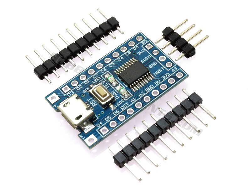
Sduino is still under development and does not currently support a good number of popular Arduino libraries, but it supports enough to be useful. So for today’s tutorial, I will examine the process involved in setting up your Arduino IDE to program an STM8 based microcontroller. For demonstration purposes, we will use the STM8S103F Development Board, and our goal will be to upload the blink example to the board.
Ready? let’s go
Required Components
The following components are required to follow this tutorial:
- The STM8S103F Development Board
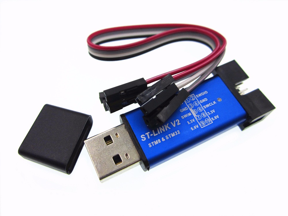
- The ST link V2 programmer
- A breadboard
- Jumper wires
All of these components can be bought from your favorite electronics component store. We will use the LED onboard the STM8S103F development board, but if you will like to use a normal LED, you can add a LED and a 220 ohms current limiting resistor to the list of components.
Schematics
Since we will implement the blink example using the LED onboard the STM8S103F, there is not much to do in terms of schematics. However, for those who may not be familiar with the process of connecting the ST link programmer to the STM8S103F board, the connection is described in the schematics below:
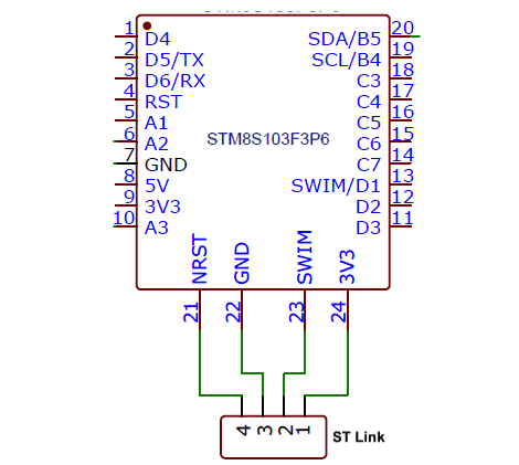
For clarity, a pin map showing how the components are connected is provided below;
ST-Link V2 –STM8S103F3
1(3.3v) - 3v3
2(SWIM) - SWIM
3(GND) - GND
4(RST) - NRST
Go over the connections again to ensure everything is as it should be. If you are using the ST-Link for the first time, you will be required to install the driver and set things up. In most situations, driver installations will start automatically immediately you connect the ST-Link programmer to your computer.
Arduino IDE Setup
To make the process of integrating open-source boards with the Arduino IDE easier, the IDE comes with a feature called “board manager“. Through the board manager, new boards (essentially software-based components required for the Arduino IDE to be able to upload code to a particular MCU) can be added to the IDE. These software-based components, often called cores, are usually developed by manufacturers of the board (like Sparkfun does for its boards) or a group of users with the desire to see their board work with the Arduino IDE. The Sduino represents the core for the STM8s boards and we will be installing it on the Arduino IDE using the board manager. Follow the steps below to do this:
1. Open the preferences window from the Arduino IDE. Go to File > Preferences
2. On the preferences window, locate the “Additional Board Manager URLs” text box and enter this link; https://github.com/tenbaht/sduino/raw/master/package_sduino_stm8_index.json into the field as shown below. As you may have other URLs there already, separate the URLs from each other using a comma (“,”) and click OK when done.
3. Next, open the Arduino board manager. Go to tools>Boards>Boards manager
4. When the board manager opens up, enter Sduino into the search bar. You should see the Sduino core come up as shown in the image below. Click on the install button to install the core.
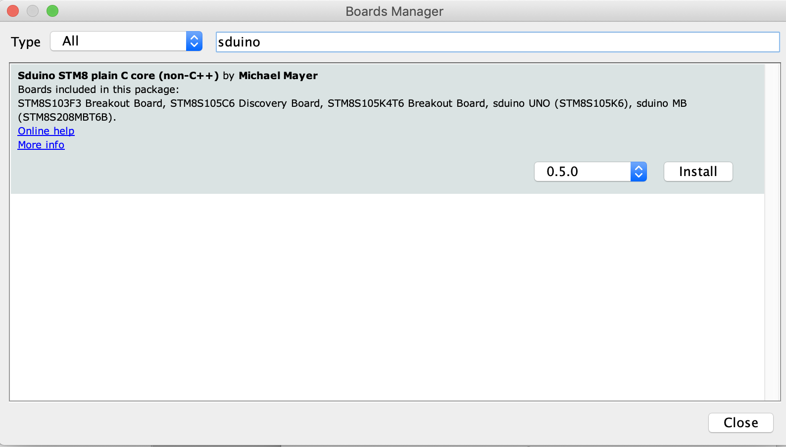
5. With the installation complete, close the board manager. The STM8s boards should now be available under the list of boards as shown in the image below.
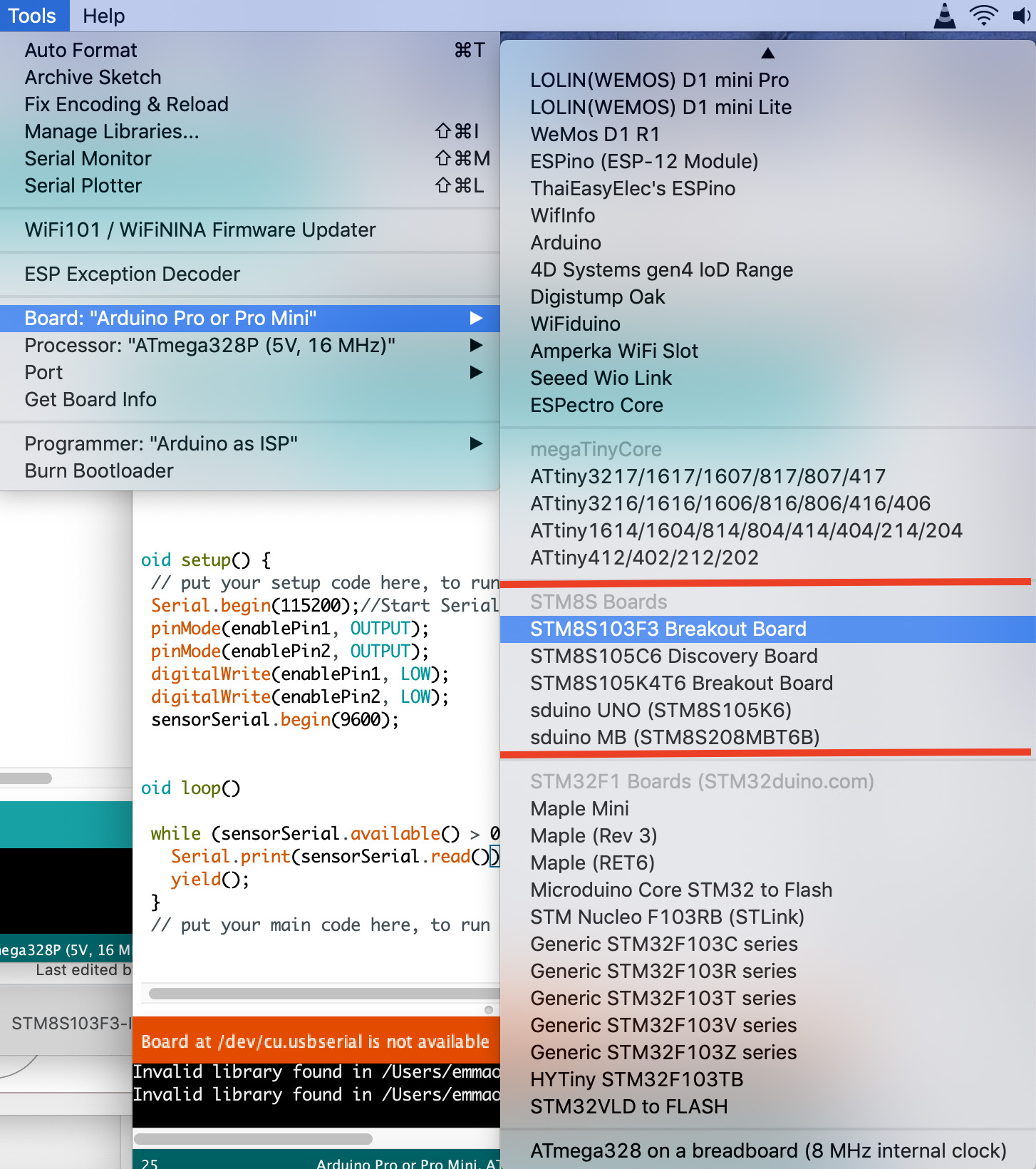
6. Installing the Sduino core will automatically install some Arduino libraries that have been modified to work with STM8s boards. Set your board type (by going to tools -> boards) to one of the STM8s boards, and go to examples (File -> examples). You will see a list of examples for the newly installed libraries.
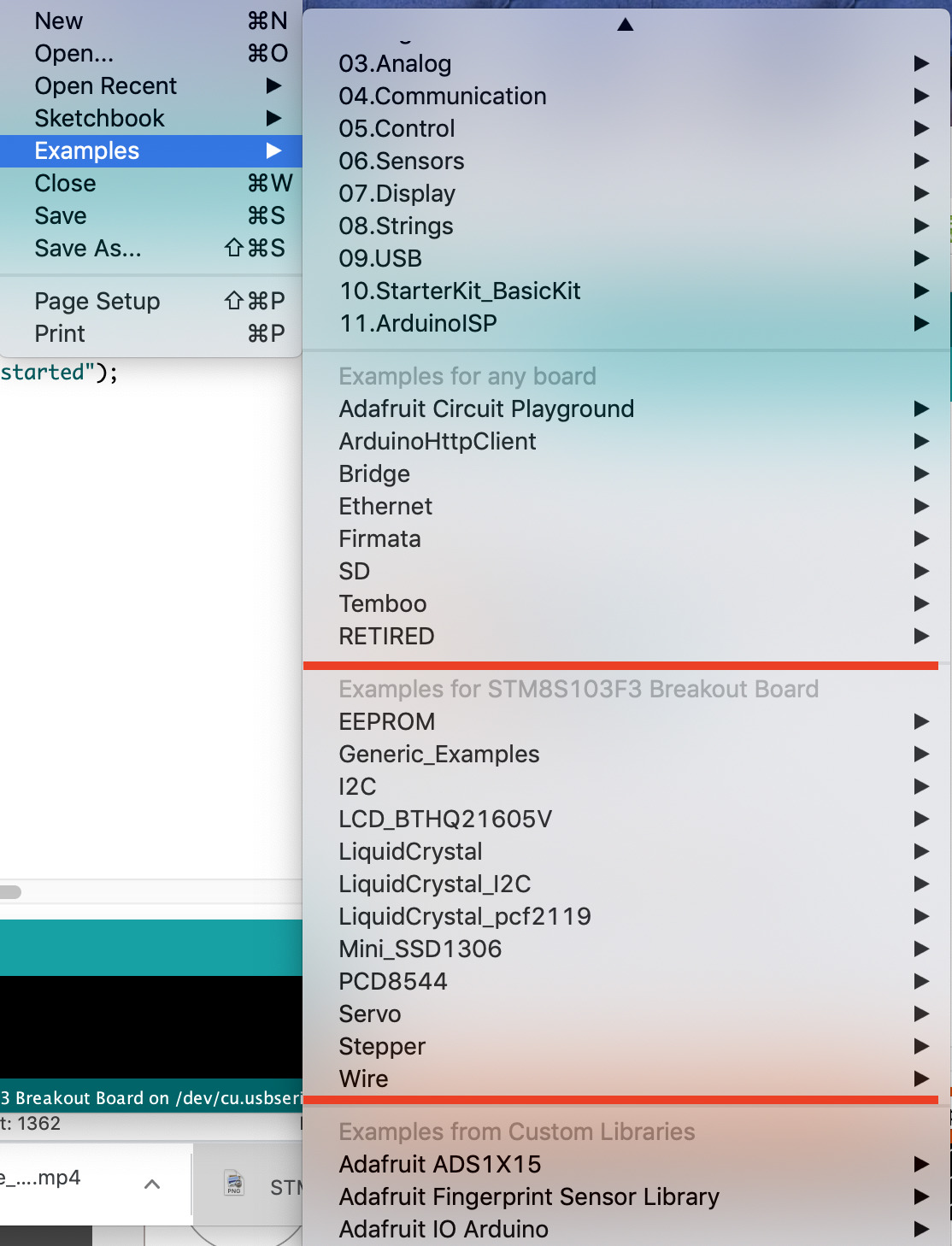
With this done, you now have all you need to upload code to the STM8s boards.
Code
As mentioned during the introduction, for demonstration purposes, we will upload the blink example to the STM8S103F Development Board. You can use the generic blink example (File -> Example -> Basics -> Blink) or use the blink example among the STM8s Specific libraries (File -> Example -> Generic_Example -> Basics -> Blink).
I believe the code for the blink example needs no explanation and if you compare the two sketches you will see that they are exactly the same.
void setup() {
  // initialize digital pin LED_BUILTIN as an output.
  pinMode(LED_BUILTIN, OUTPUT);
}
// the loop function runs over and over again forever
void loop() {
  digitalWrite(LED_BUILTIN, HIGH);   // turn the LED on (HIGH is the voltage level)
  delay(1000);                       // wait for a second
  digitalWrite(LED_BUILTIN, LOW);    // turn the LED off by making the voltage LOW
  delay(1000);                       // wait for a second
}
Code Upload
Ensure your board is connected to the computer via the ST-link as described in the schematics. On the Arduino IDE, ensure the right board type is selected, and for set the programmer to ST-Link/V2 as shown in the image below:
With this done, hit the upload button, you should see the onboard LED begin to blink.
That’s it!
The Arduino IDE and Sduino provides a pathway to help you jumpstart development with STM8S. However, the platform is still under development and many Arduino libraries are yet to be supported.
That’s it for this tutorial! feel free to reach out to me via the comment section with questions or any clarifications you require.


Hey, great article. Is there a core for STM8L family? Or this one would work with it too?
the blink code is working but when i use other program like Ultrasonic sensor code it give me error “Error compiling for board STM8S103F3 Breakout Board”
Hey is it also possible to add the the STM8L series to Arduino? I have a STM8L051F3 I would like to add as a board. Is that possible?
Thanks, works good. ST Visual Programmer also uploads the compiled binary hex file generated by the Arduino IDE. I am using the STM8S003F3 board with SWIM interface.