RC PWM Signal to Stepper Pulse Generator
- Rajkumar Sharma
- 115 Views
- moderate
- Tested
- SKU: EL150101
- Quote Now
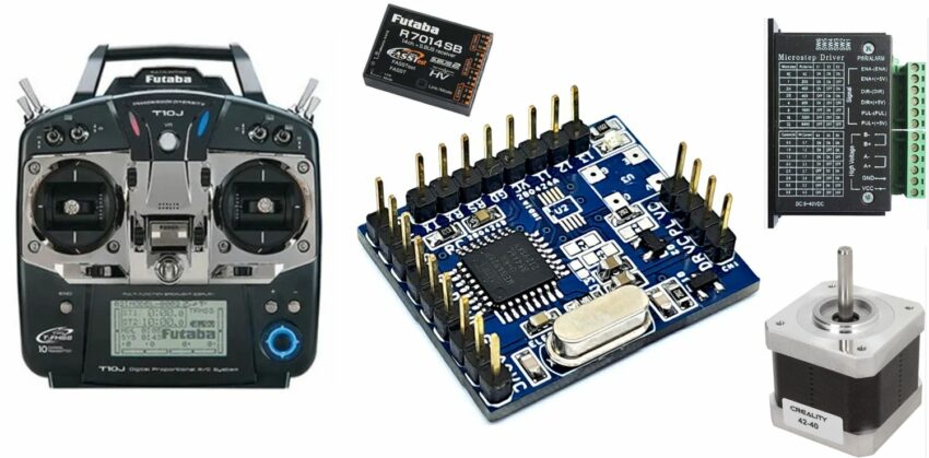
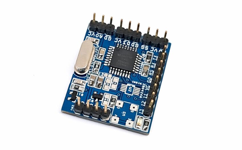
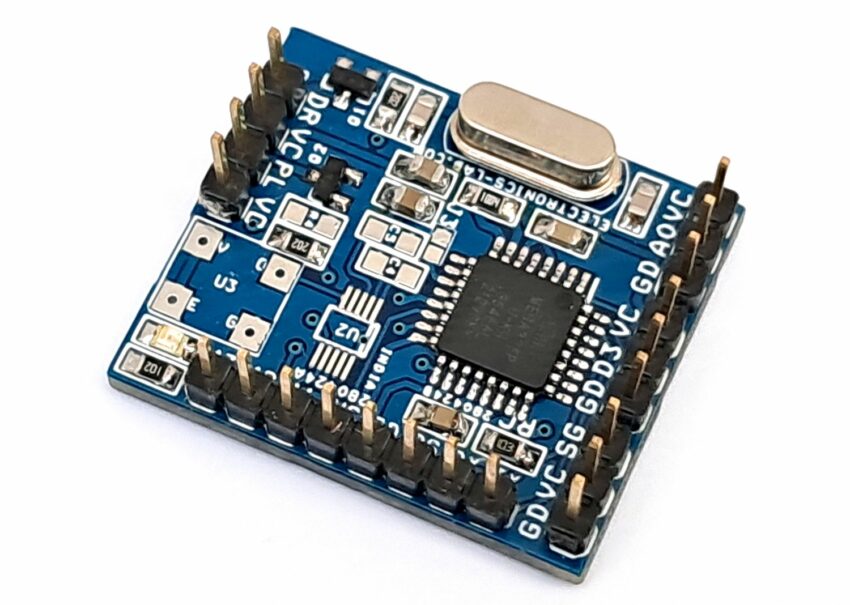
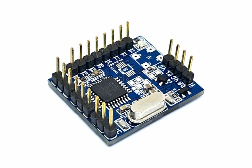
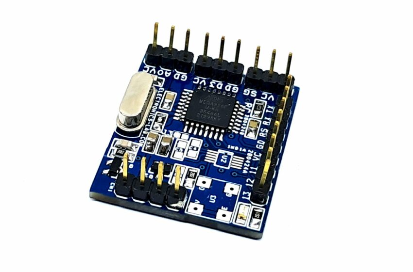
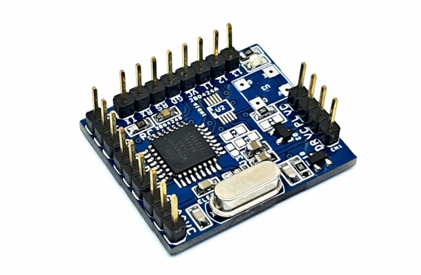
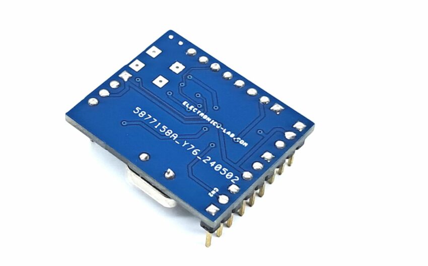
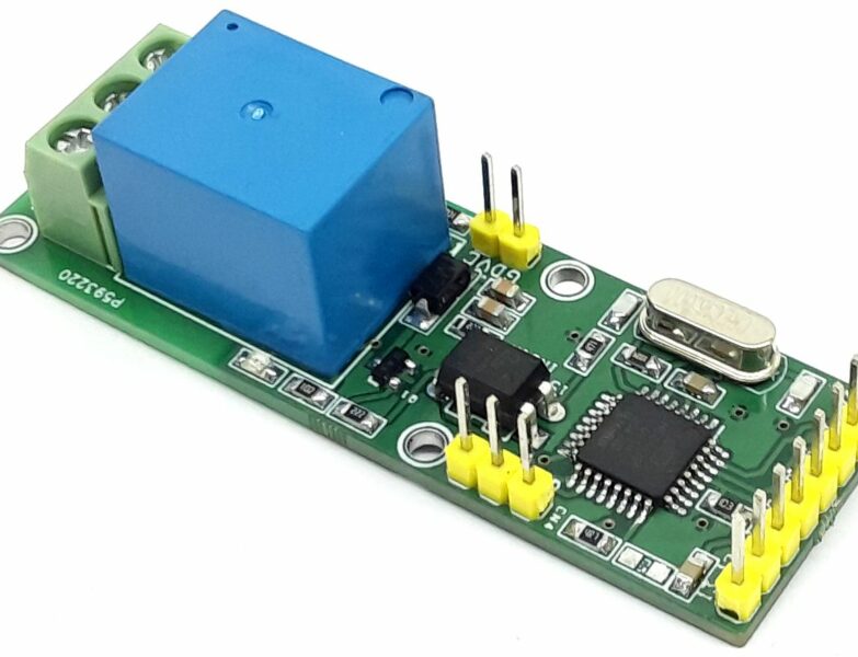
This simple Arduino compatible project reads an RC PWM signal (1000μs to 2000μs) and provides 0 to 500Hz pulse output to drive a stepper motor. Step and Direction outputs are open collector types 5V signals. Both signals can directly drive LEDs of optocoupler of stepper drivers. The board consists of ATMEGA328 chip and 2 x BC847 transistors. The transistor helps drive the optocouplers.
Arduino Code
A sample Arduino code is available to test the project.
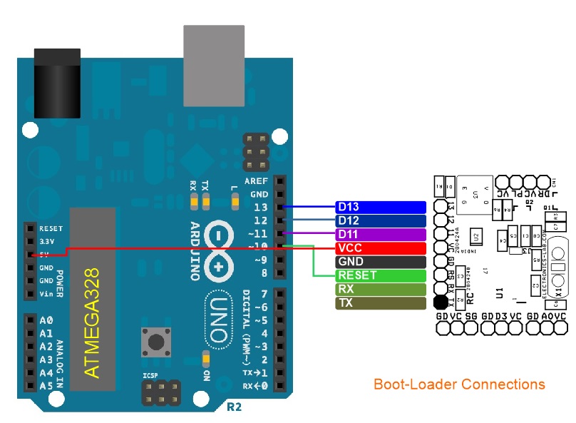
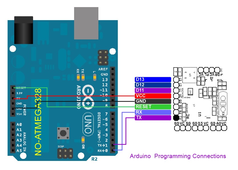
Burn the bootloader and Arduino code into the new ATMEGA328 microcontroller using an onboard programming connector. Refer to the bootloader and Arduino programming diagram for Connections.
Credits: This is modified code, original code written by: Brandon Tsuge (theboredrobot.com)
Bootloader information: https://docs.arduino.cc/retired/hacking/software/Bootloader/
Arduino Bootloader and Arduino Programming: https://docs.arduino.cc/built-in-examples/arduino-isp/ArduinoToBreadboard/
Features
- Power Supply 5V DC @ 30mA
- Outputs are Capable to Drive 5V TTL Load (Step/Dir)
- Outputs are Open Collector Type
- RC PWM Signal Range 1000μs To 2000μs
- Output Frequency 0 to 500Hz
- On Board Header Connector for Bootloader and Arduino Programming
- Very Small Board
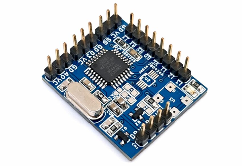
- PCB Dimensions 30.32 x 25.72mm
Connections
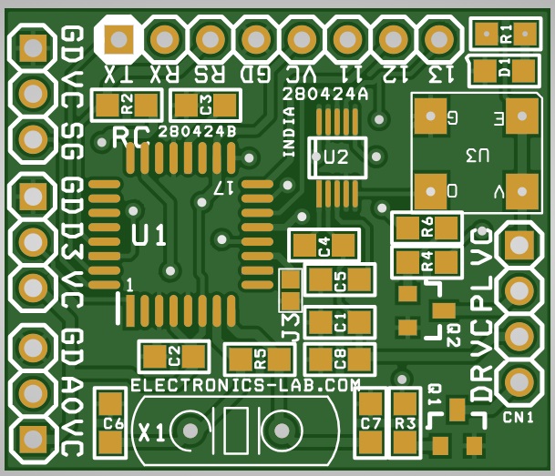
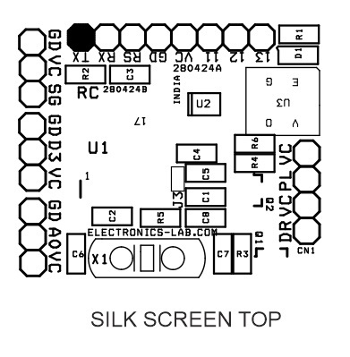
- CN1: Pin 1 5V, Pin 2 = Step Pules Output, Pin 3 = 5V, Pin 4 = Dir
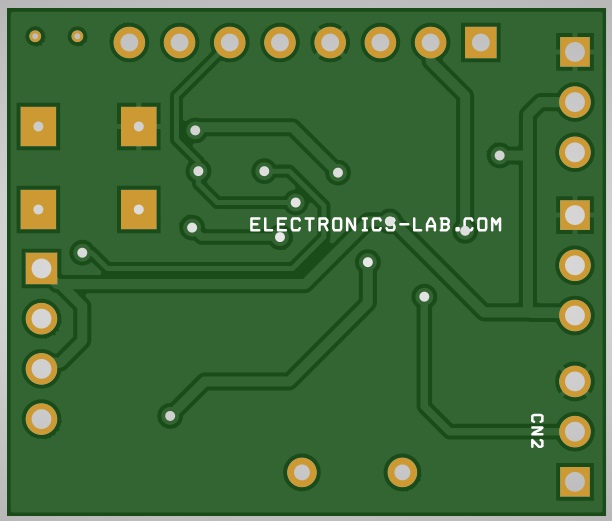
- CN2: Do Note Install (Can be configured as Limit Switch)
- J1: RC Signal Input, Pin 1 = RC Signal Input, Pin 2 = VCC, Pin 3 = GND
- J2: Do Note Install (Can be configured as Limit Switch)
- CN3: Programming Connector Pin 1 = TX, Pin 2 RX, Pin 3 Reset, Pin 4 = GND, Pin 5 = VCC/5V, Pin 6 = D11, Pin 7 = D12, Pin 8 = D13
- D1: Power LED
Schematic
Parts List
| NO. | QNTY. | REF, | DESC. | MANUFACTURER | SUPPLIER | SUPPLIER PART NO |
|---|---|---|---|---|---|---|
| 1 | 1 | CN1 | 4 PIN MALE HEADER PITCH 2.54MM | WURTH | DIGIKEY | 732-5317-ND |
| 2 | 6 | U2,J2,CN2,U3,R4,C4 | DNP | DO NOT INSTALL | ||
| 3 | 1 | CN3 | 8 PIN MALE HEADER PITCH 2.54MM | WURTH | DIGIKEY | 732-5321-ND |
| 4 | 2 | C1,C8 | 10uF/10V CERAMIC SMD SIZE 0805 | YAGEO/MURATA | DIGIKEY | |
| 5 | 3 | C2,C3,C5 | 0.1uF/50V CERAMD SIZE 0805MIC | YAGEO/MURATA | DIGIKEY | |
| 6 | 2 | C6,C7 | 22PF/50V CERAMIC SMD SIZE 0805 | YAGEO/MURATA | DIGIKEY | |
| 7 | 1 | D1 | LED SMD SIZE 0805 | OSRAM | DIGIKEY | 475-1278-1-ND |
| 8 | 1 | J1 | 3 PIN MALE HEADER PITCH 2.54MM | WURTH | DIGIKEY | 732-5316-ND |
| 9 | 1 | J3 | SOLDER JUMPER-PCB | NO USE | ||
| 10 | 2 | Q1,Q2 | BC847 | NEXPERIA | DIGIKEY | 1727-2924-2-ND |
| 11 | 1 | R1 | 1K 5% SMD SIZE 0805 | YAGEO/MURATA | DIGIKEY | |
| 12 | 1 | R2 | 10K 5% SMD SIZE 0805 | YAGEO/MURATA | DIGIKEY | |
| 13 | 2 | R3,R6 | 2.2K 5% SMD SIZE 0805 | YAGEO/MURATA | DIGIKEY | |
| 14 | 1 | R5 | 1M 5% SMD SIZE 0805 | YAGEO/MURATA | DIGIKEY | |
| 15 | 1 | U1 | ATMEGA328TQPF-32 | MICROCHIP | DIGIKEY | ATMEGA328PB-AURCT-ND |
| 16 | 1 | X1 | 16Mhz | ECS INC | DIGIKEY | X1103-ND |
Connections


