Use RC522 RFID module with Arduino and an OLED display – RFID lock
- Nick Koumaris
- http://educ8s.tv
- info@educ8s.tv
- 15.270 Views
- moderate
- Tested
RFID is one of these technologies that change how we interact with other electronic devices and things in our environment. It is used in every application where some unique identifier is required, from retail to security and is also leading the path along several futuristic innovations with RFID based human implants among others. This wide range of applications makes RFID desirable and useful for several Arduino projects. For today’s tutorial, we will look on how to use RFID in Arduino based projects.
How it works
Before we dive into the project, it’s probably important to do an introduction on RFID. RFID stands for Radio Frequency Identification System. It comprises of two main parts; the reader (and ofteb writer) and the tags. The readers use electromagnetic field to automatically identify and track electronically stored, information contained in tags. Some of these readers also come with writing ability which enables them to change the information stored on compatible tags within their proximity.
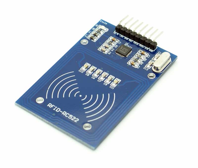
The tags, on the other hand, carry pre-stored information from writers and send this info to the reader when requested. Each RFID tag has a small chip inside, which can usually be seen if a flashlight is placed under the tag. All the information in the tag is stored on the chip, including a unique number (known as the UID) through which the tags are identified and differentiated from each other. RFID tags can either be passive or active. Passive tags are usually short range and have no power source embedded. They are powered via induction from the electromagnetic field of the reader when they are in range and information is transmitted to them. Active tags, however, are usually battery powered and are capable of communicating with readers over longer distances.
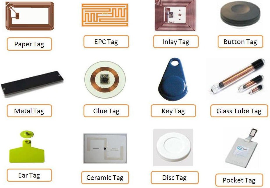
For today’s tutorials, we will use the RC522 RFID reader to obtain the UID of tags placed near it and to create a simple prototype of an RFID based door lock system. The RC522 RFID reader is a low cost, highly integrated, 13.56 MHz contactless communication enabled reader module. It is by far one of the most popular RFID readers among hobbyists and makers due to its low cost and ease of use with the Arduino. Some of the features of the RFID reader are described below:
- MFRC522 chip based board
- Operating frequency: 13.56MHz
- Supply Voltage: 3.3V
- Current: 13-26mA
- Read Range: Approx 3cm
- SPI Interface
- Max Data Transfer Rate: 10Mbit / s
- Dimensions: 60mm × 39mm
At the end of this tutorial, you will know how to build RFID based Arduino projects.
Required Components
The following components are required to build this project:
As usual, this component can be purchased via the links attached to them.
Schematics
The schematic for this project is quite simple. The RFID module uses the SPI communication protocol, so it will be connected to the dedicated SPI pins on the Arduino. The OLED display, on the other hand, uses I2C protocol and will thus also be connected to the Arduino’s dedicated I2C lines. Connect the component as shown in the schematics below.
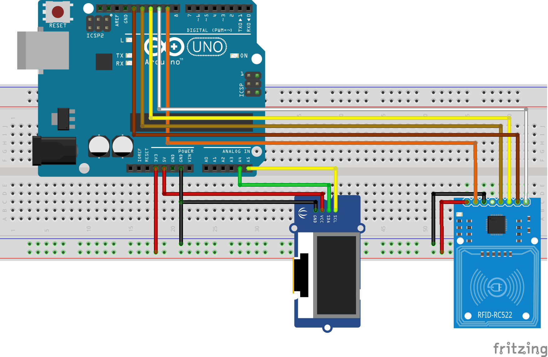
To make the schematics easier to follow, the pin connections between the Arduino and other components are described below.
RC522 – Arduino
SDA - D10
SCK - D13
MOSI - D11
MISO - D12
IRQ - Not connected
GND - GND
RST - D9
3.3V - 3.3V
OLED – Arduino
SCL - A5
SDA - A4
VCC - 5v
GND - GND
The OLED display has been used in many tutorials on this website. You can check them out to learn more about using OLED displays.
Go over your connections once again to be sure everything is as it should be. The final setup after the connections should look like the image below.
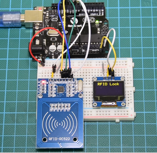
The RC522 module may be damaged if connected to a voltage above 3.3v so ensure it is rightly connected.
Code
To simplify and reduce the amount of code needed for this project, we will use the MFRC522 library, the Adafruit SD1306, and the Adafruit GFX libraries. For everyone running the latest version of the Arduino IDE, you can download these libraries via the library manager. Go to “Sketch -> Include Libraries -> Manage libraries” and enter the name of the libraries into the search bar and install them one after the other. With the libraries installed, go to your libraries folder and open the Adafruit_SSD1306.h using any code editor like notepad++. We will change the default screen resolution to match that of our display (128×64) by commenting out the default value (128×32) and un-commenting the line that matches our display as shown in the image below.
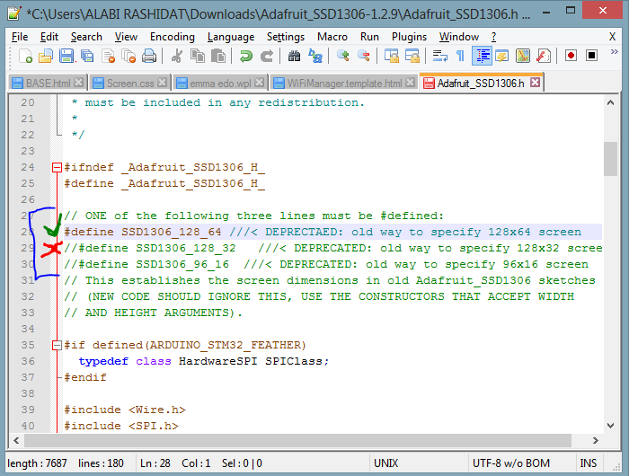
With this done, save and relaunch the IDE. We are now ready for the code.
The code for this project is quite easy and as mentioned during the introduction, we will read tags and check if they match pre-stored UIDs. If there is a match, “unlocked” will be displayed on the OLED display and if there is no match, the OLED will display “locked”, simulating the actions on an RFID based door lock system.
As usual, I will do a quick break down of the code and try as much as possible to explain all the key parts of the code. We start by including the libraries that will use as discussed above.
//Written by Nick Koumaris
//info@educ8s.tv

#include <MFRC522.h>
#include <Adafruit_GFX.h>
#include <Adafruit_SSD1306.h>
#include <SPI.h>
Next, we create an instance of the SSD1306 library for the OLED display, declare the pins of the Arduino to which the reader is connected and create an instance of the MFRC522 library.
#define OLED_RESET 4
Adafruit_SSD1306 display(OLED_RESET);

#define SS_PIN 10
#define RST_PIN 9

MFRC522 rfid(SS_PIN, RST_PIN); // Instance of the class

MFRC522::MIFARE_Key key;
Next, we declare the UID (an array of integers) of the RFID tag, that we want the Arduino to recognize and other variables that will be used in the code.
int code[] = {69,141,8,136}; //This is the stored UID
int codeRead = 0;
String uidString;
Next, we write the void setup function where we initialize the RFID reader and the display. Serial, SPI and I2C communications are also initiated and we set the system to start in lock mode, waiting for tags to be scanned.
void setup() {

  Serial.begin(9600);
  SPI.begin(); // Init SPI bus
  rfid.PCD_Init(); // Init MFRC522

  display.begin(SSD1306_SWITCHCAPVCC, 0x3C);  // initialize with the I2C addr 0x3D (for the 128x64)

  // Clear the buffer.
  display.clearDisplay();
  display.display();
  display.setTextColor(WHITE); // or BLACK);
  display.setTextSize(2);
  display.setCursor(10,0);
  display.print("RFID Lock");
  display.display();

}
Next, is the void loop() function. The loop function simply calls the readrfid function whenever the RFID reader detects an RFID card with a delay of 100ms between calls to allow the information from the tags to be processed.
void loop() {
  if(  rfid.PICC_IsNewCardPresent())
  {
      readRFID();
  }
  delay(100);

}
The readrfid function does all the heavy lifting associated with this project. The function is quite long but, it simply extracts the UID of the tag being scanned and checks if it matches the stored UID. If there is a match, the unlock message is printed, while if there is not a match, the system stays locked.
void readRFID()
{

  rfid.PICC_ReadCardSerial();
  Serial.print(F("\nPICC type: "));
  MFRC522::PICC_Type piccType = rfid.PICC_GetType(rfid.uid.sak);
  Serial.println(rfid.PICC_GetTypeName(piccType));

  // Check is the PICC of Classic MIFARE type
  if (piccType != MFRC522::PICC_TYPE_MIFARE_MINI &&
    piccType != MFRC522::PICC_TYPE_MIFARE_1K &&
    piccType != MFRC522::PICC_TYPE_MIFARE_4K) {
    Serial.println(F("Your tag is not of type MIFARE Classic."));
    return;
  }

    clearUID();

    Serial.println("Scanned PICC's UID:");
    printDec(rfid.uid.uidByte, rfid.uid.size);

    uidString = String(rfid.uid.uidByte[0])+" "+String(rfid.uid.uidByte[1])+" "+String(rfid.uid.uidByte[2])+ " "+String(rfid.uid.uidByte[3]);

    printUID();

    int i = 0;
    boolean match = true;
    while(i<rfid.uid.size)
    {
      if(!(rfid.uid.uidByte[i] == code[i]))
      {
           match = false;
      }
      i++;
    }

    if(match)
    {
      Serial.println("\nI know this card!");
      printUnlockMessage();
    }else
    {
      Serial.println("\nUnknown Card");
    }


    // Halt PICC
  rfid.PICC_HaltA();

  // Stop encryption on PCD
  rfid.PCD_StopCrypto1();
}
other functions used include the printUID() function and the printunlockmessage() function which should be easy to follow.
The complete code for the project is shown below.
//Written by Nick Koumaris
//info@educ8s.tv

#include <MFRC522.h>
#include <Adafruit_GFX.h>
#include <Adafruit_SSD1306.h>
#include <SPI.h>


#define OLED_RESET 4
Adafruit_SSD1306 display(OLED_RESET);

#define SS_PIN 10
#define RST_PIN 9

MFRC522 rfid(SS_PIN, RST_PIN); // Instance of the class

MFRC522::MIFARE_Key key;

int code[] = {69,141,8,136}; //This is the stored UID
int codeRead = 0;
String uidString;
void setup() {

  Serial.begin(9600);
  SPI.begin(); // Init SPI bus
  rfid.PCD_Init(); // Init MFRC522

  display.begin(SSD1306_SWITCHCAPVCC, 0x3C);  // initialize with the I2C addr 0x3D (for the 128x64)

  // Clear the buffer.
  display.clearDisplay();
  display.display();
  display.setTextColor(WHITE); // or BLACK);
  display.setTextSize(2);
  display.setCursor(10,0);
  display.print("RFID Lock");
  display.display();

}

void loop() {
  if(  rfid.PICC_IsNewCardPresent())
  {
      readRFID();
  }
  delay(100);

}

void readRFID()
{

  rfid.PICC_ReadCardSerial();
  Serial.print(F("\nPICC type: "));
  MFRC522::PICC_Type piccType = rfid.PICC_GetType(rfid.uid.sak);
  Serial.println(rfid.PICC_GetTypeName(piccType));

  // Check is the PICC of Classic MIFARE type
  if (piccType != MFRC522::PICC_TYPE_MIFARE_MINI &&
    piccType != MFRC522::PICC_TYPE_MIFARE_1K &&
    piccType != MFRC522::PICC_TYPE_MIFARE_4K) {
    Serial.println(F("Your tag is not of type MIFARE Classic."));
    return;
  }

    clearUID();

    Serial.println("Scanned PICC's UID:");
    printDec(rfid.uid.uidByte, rfid.uid.size);

    uidString = String(rfid.uid.uidByte[0])+" "+String(rfid.uid.uidByte[1])+" "+String(rfid.uid.uidByte[2])+ " "+String(rfid.uid.uidByte[3]);

    printUID();

    int i = 0;
    boolean match = true;
    while(i<rfid.uid.size)
    {
      if(!(rfid.uid.uidByte[i] == code[i]))
      {
           match = false;
      }
      i++;
    }

    if(match)
    {
      Serial.println("\nI know this card!");
      printUnlockMessage();
    }else
    {
      Serial.println("\nUnknown Card");
    }


    // Halt PICC
  rfid.PICC_HaltA();

  // Stop encryption on PCD
  rfid.PCD_StopCrypto1();
}

void printDec(byte *buffer, byte bufferSize) {
  for (byte i = 0; i < bufferSize; i++) {
    Serial.print(buffer[i] < 0x10 ? " 0" : " ");
    Serial.print(buffer[i], DEC);
  }
}

  void clearUID()
  {
    display.setTextColor(BLACK); // or BLACK);
    display.setTextSize(1);
    display.setCursor(30,20);
    display.print(uidString);
    display.display();
  }

  void printUID()
  {
    display.setTextColor(WHITE); // or BLACK);
    display.setTextSize(1);
    display.setCursor(0,20);
    display.print("UID: ");
    display.setCursor(30,20);
    display.print(uidString);
    display.display();
  }

  void printUnlockMessage()
  {
    display.display();
    display.setTextColor(BLACK); // or BLACK);
    display.setTextSize(2);
    display.setCursor(10,0);
    display.print("RFID Lock");
    display.display();

    display.setTextColor(WHITE); // or BLACK);
    display.setTextSize(2);
    display.setCursor(10,0);
    display.print("Unlocked");
    display.display();

    delay(2000);

    display.setTextColor(BLACK); // or BLACK);
    display.setTextSize(2);
    display.setCursor(10,0);
    display.print("Unlocked");

    display.setTextColor(WHITE); // or BLACK);
    display.setTextSize(2);
    display.setCursor(10,0);
    display.print("RFID Lock");
    display.display();
  }
Demo
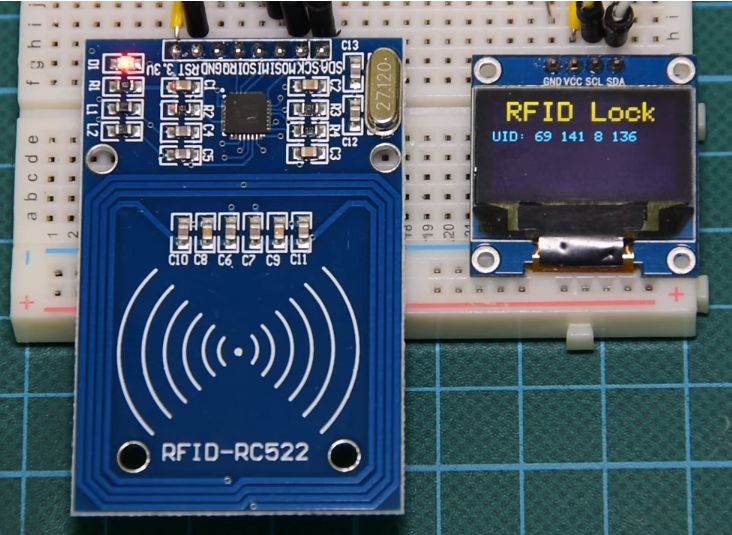
Go over the schematics and ensure the components are properly connected, then upload the code to the Arduino board. Ensure the libraries have been installed as described and the modifications to the SD1306 library has been made as described. After Uploading, you should see the OLED come up as shown below.
Put the card with the known UID across the RFID reader and you should see the screen indicate “Unlocked”. After a few minutes, It will go back to “locked” and you can then scan an unknown tag and see the outcome.
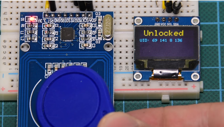
That’s it for this tutorial guys. As simple as it may seem, RFIDs have applications in diverse industries from security to retail and the example we just built, could serve as building block for an RFID based door lock system or a retail solution. What RFID application are you most interested in? do share via the comment section along with questions and other comments.
Till Next time!
The video version of this tutorial is available on youtube.




great tutorial, just wondering how to add multiple tag uid’s so i can use more than one card or tag.
Musisz napisać więcej warunków z twoimi UID czyli takie:
int code[] = {00,000,0,000}; //tu zapisz swój UID