RGB LED Controller using Atmega328
- Rajkumar Sharma
- 4.410 Views
- moderate
- Tested
- SKU: EL102006
- Quote Now
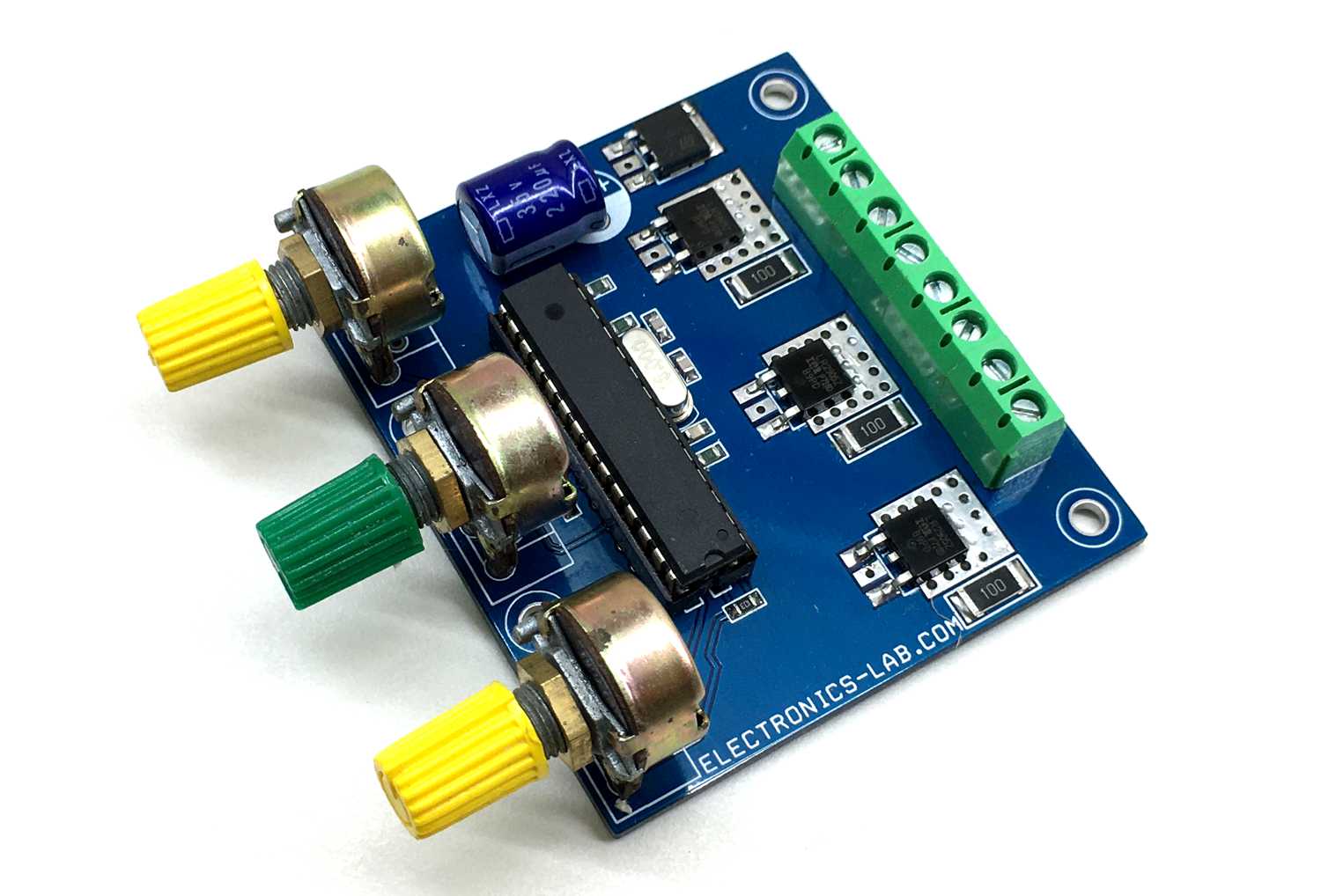
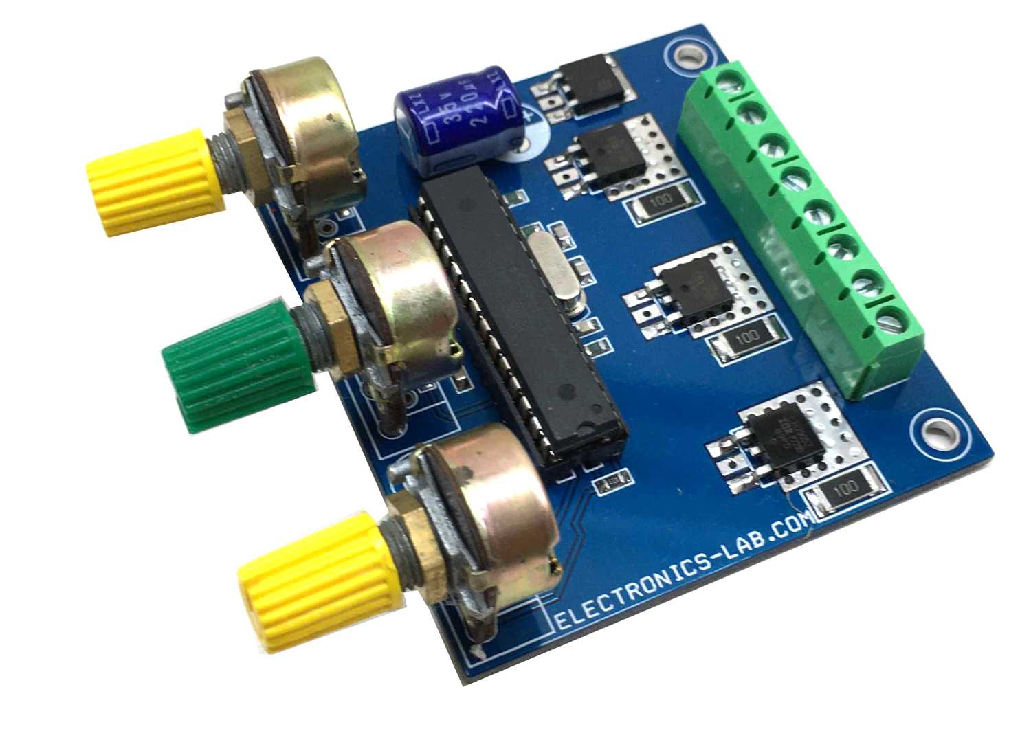
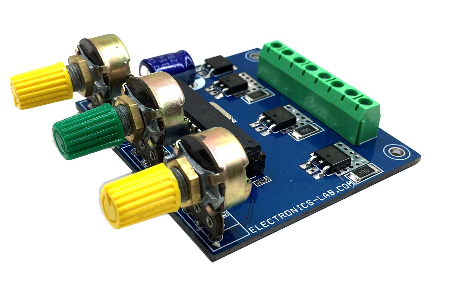
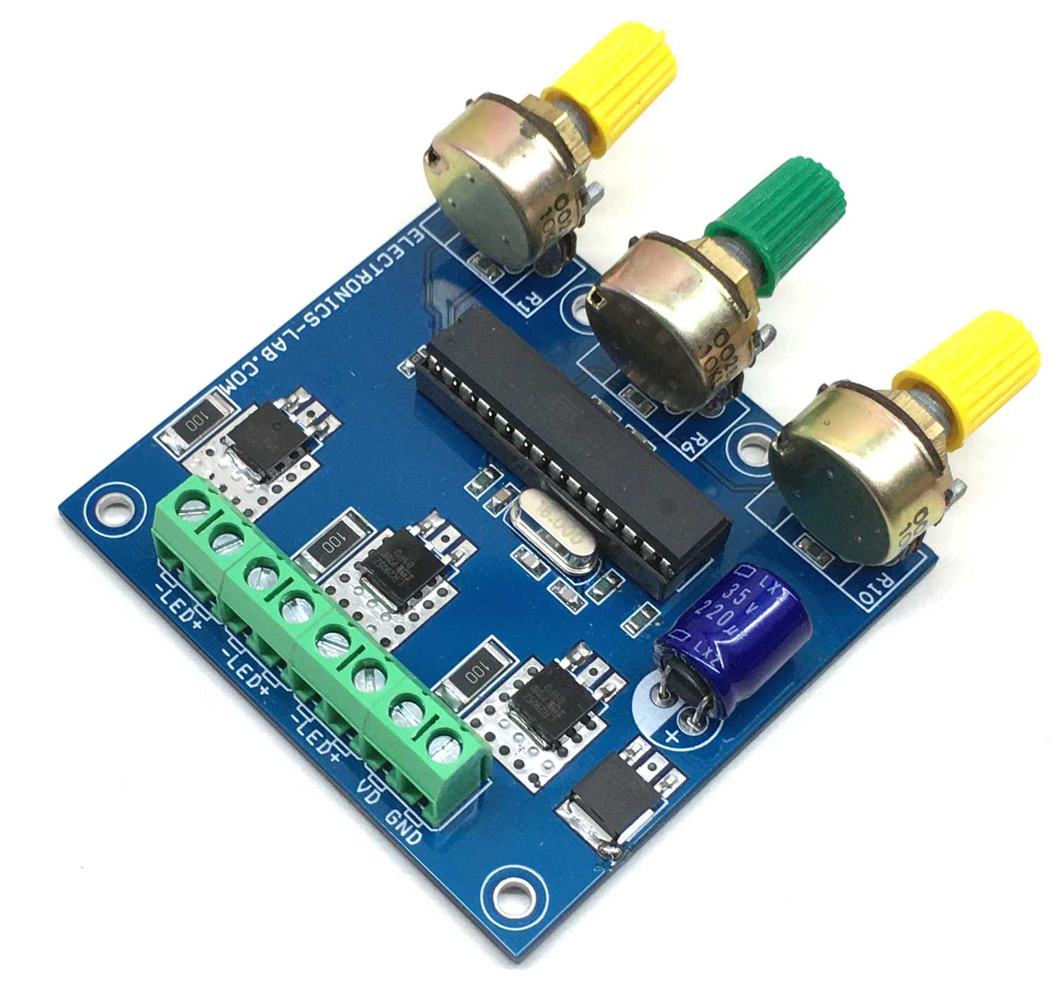
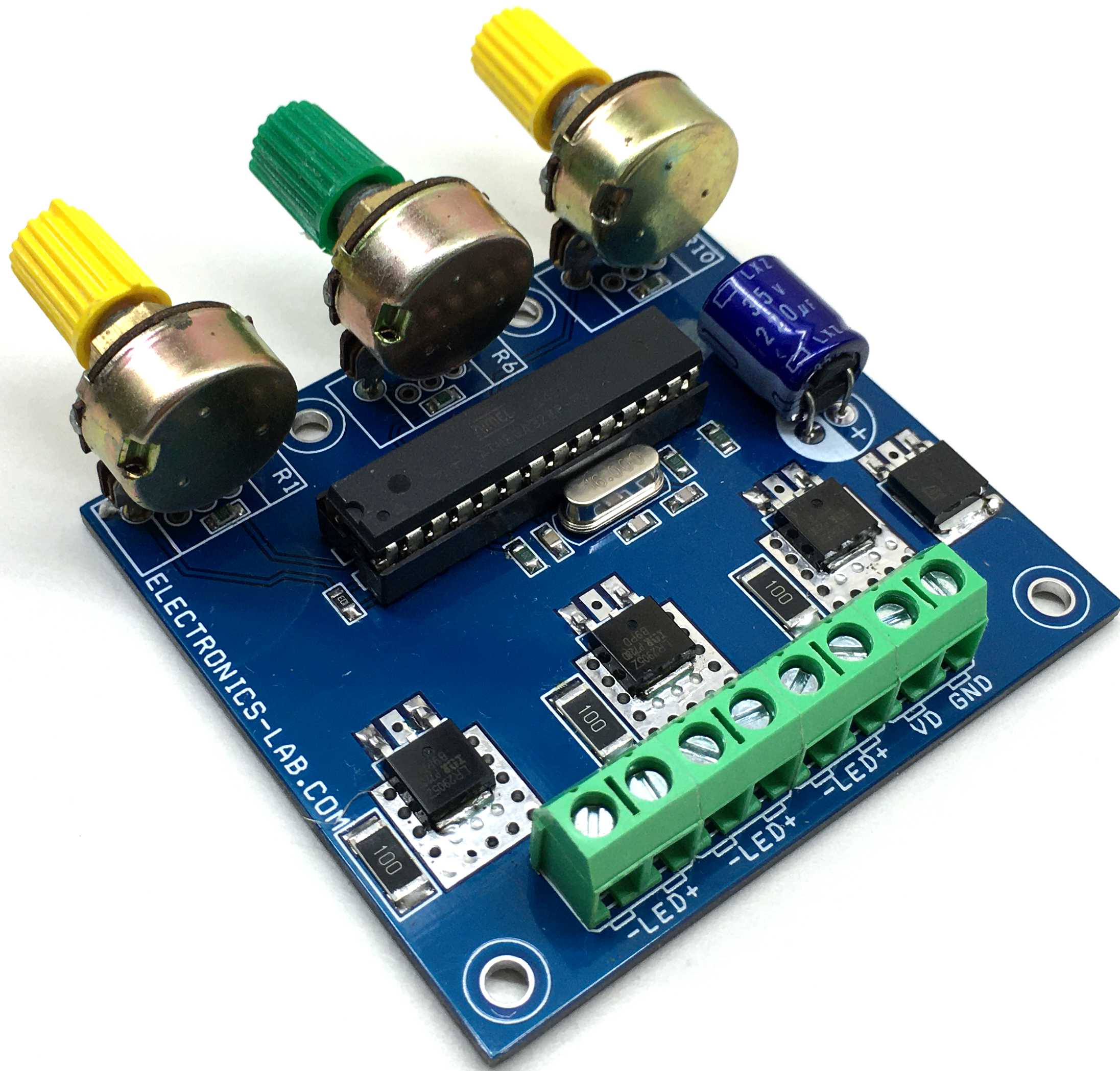
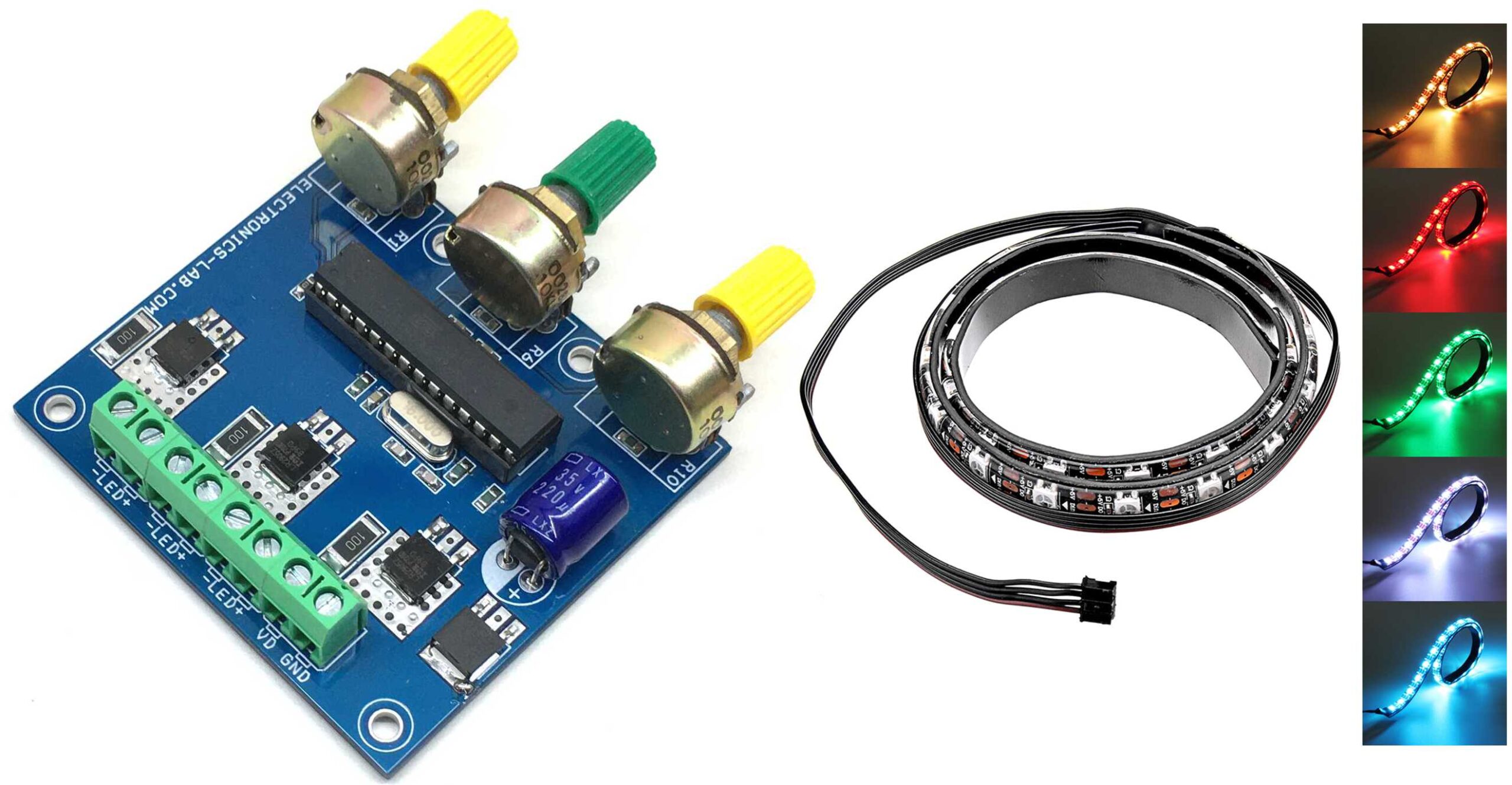
This is a 3-channel, PWM based current-adjustable LED driver designed for RGB LED control. The circuit has been designed to control high current RGB LEDs or RGB LEDs strip. Colors of the three RGB LEDs can be set using 3 potentiometers, different colors are possible by adjusting these potentiometers.
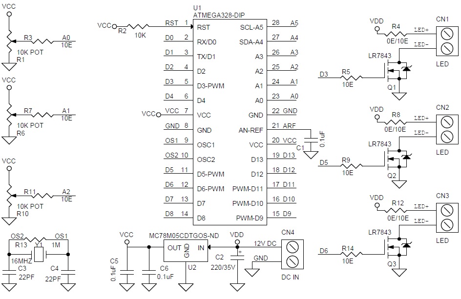
We have used ATmega328 microcontroller to generate 3 PWM signals by reading analog inputs. These analog inputs are connected to 3 potentiometers. PWM outputs interfaced with gates of 3 x IRLR7843 MOSFETs which drive the high current loads. MC78M05 IC used to power the Atmega328 chip with 5V DC. The operating voltage of this circuit is 12V DC and each channel can drive a continuous load current up to 600mA or 1 A with cool air. Screw terminals provided for an easy connection for RGB LED strip or RGB LEDs. The circuit can drive 12V RGB strip/12V RGB LEDs. Any RGB LED strip with RGB and +V connection will work with this board or use a common anode RGB LED.
This project is built using an Atmega328 microcontroller which requires programming, example code can be found below. This example code is written using Arduino IDE, thus the Atmega328 chip requires boot-loader burning and code uploading. Follow this link to learn Atmega328 Chip programming and Boot-Loader burning.
- From Arduino to a Microcontroller on a Breadboard – https://www.arduino.cc/en/Tutorial/BuiltInExamples/ArduinoToBreadboard
Features
- Supply 12V DC (7V-15V)
- Load 600mA Each channel (1Amp with Fan)
- 3x Potentiometer to Adjust 3X LEDs
- PWM Duty Cycle Adjustable 0% to 100%
- Frequency 490/975 Hz
- Arduino Compatible Code
- PCB Dimensions 61 X 67 mm
Schematic
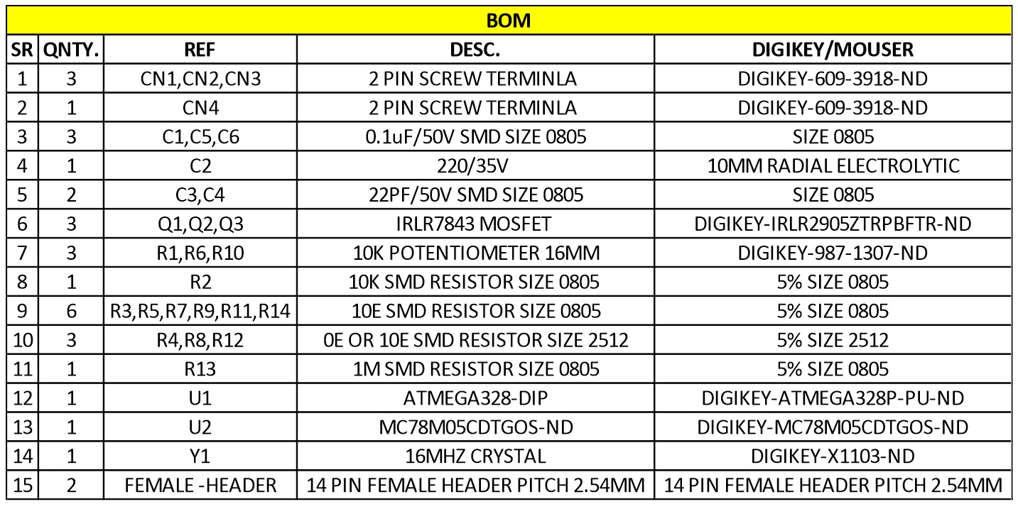
Parts List
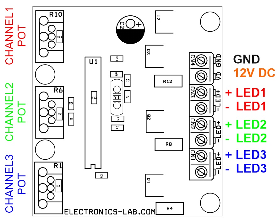
Connections
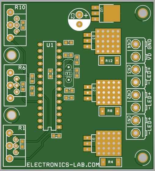
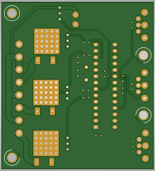
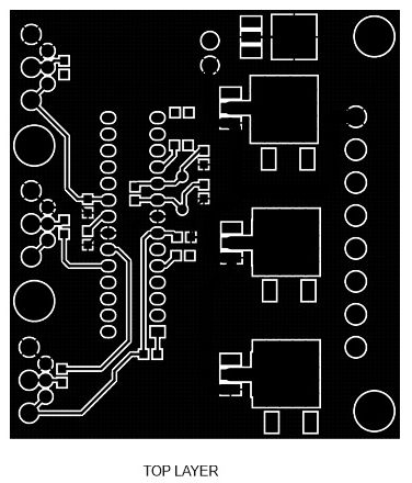
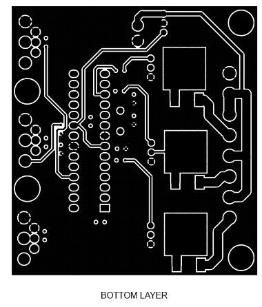
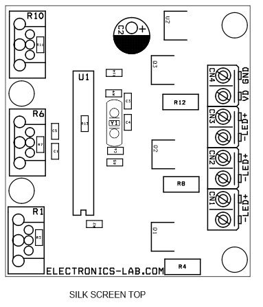
Gerber View
Photos
Video






Why dont you add a screen that displays 0-255 color values of those colors?
please i would like to have a flowchart of the code
Can you contact me via email?