Signal Conditioning Module for Magnetic Rotary Encoder with Clock and Up/Down Direction Signal Output
- Rajkumar Sharma
- 340 Views
- moderate
- Tested
- SKU: EL135483
- Quote Now
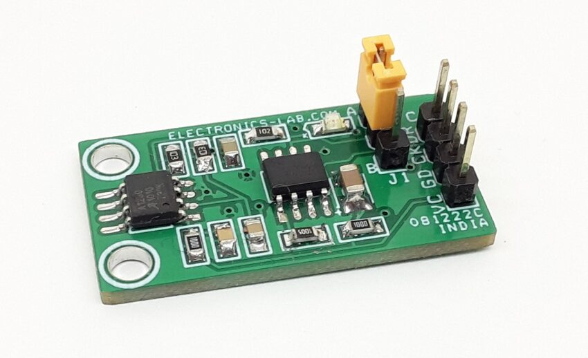
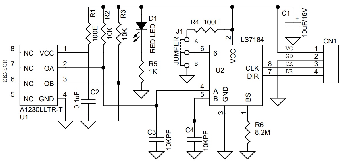
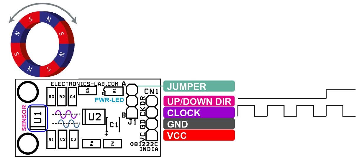
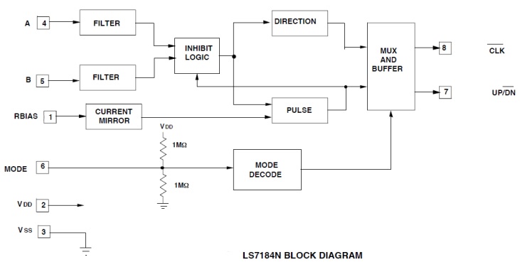
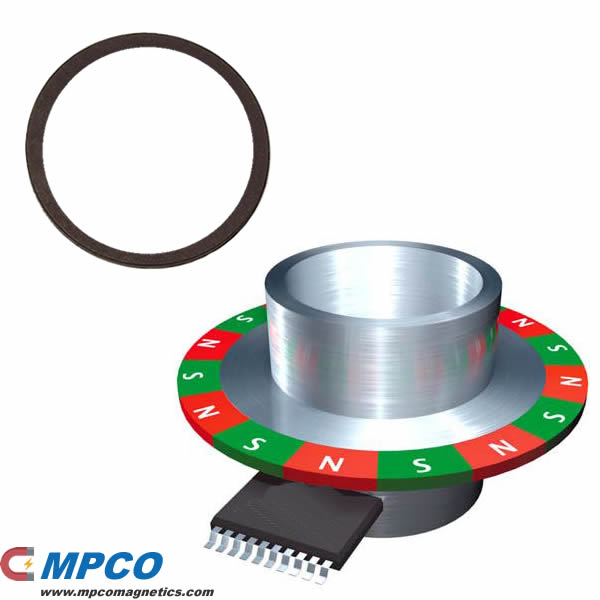
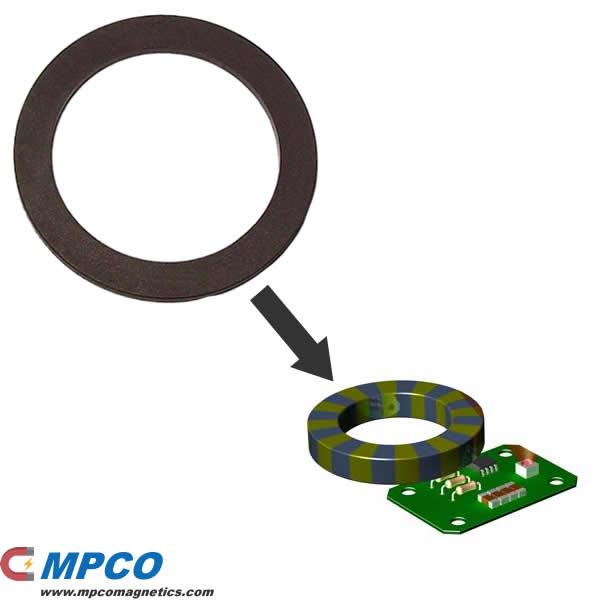
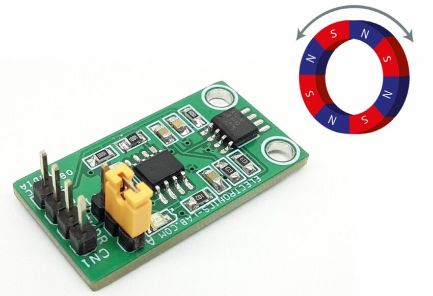
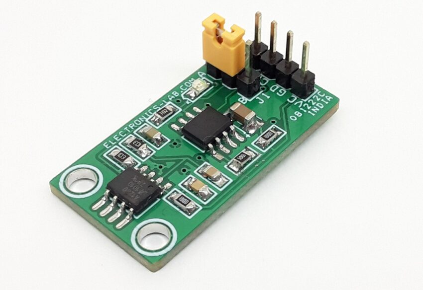
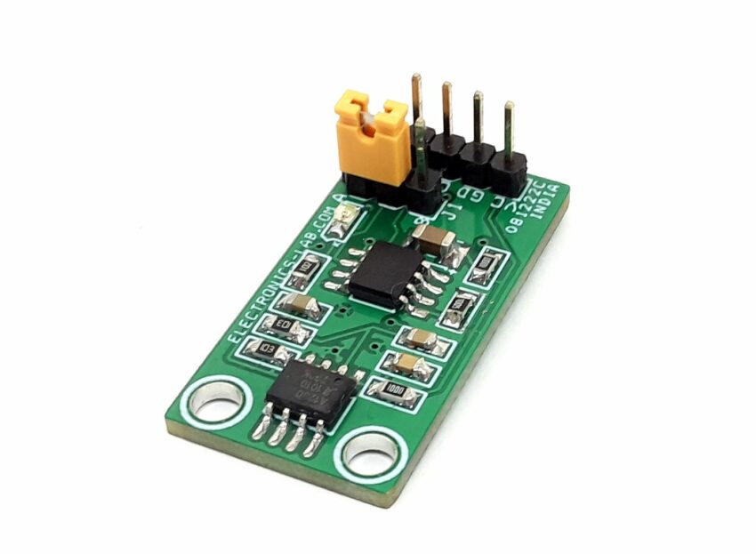
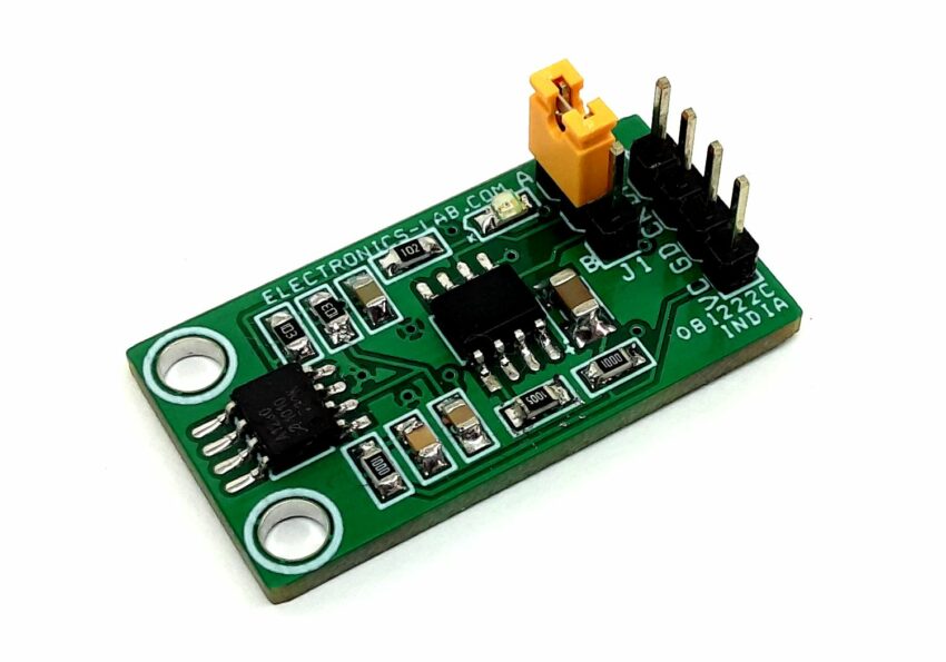
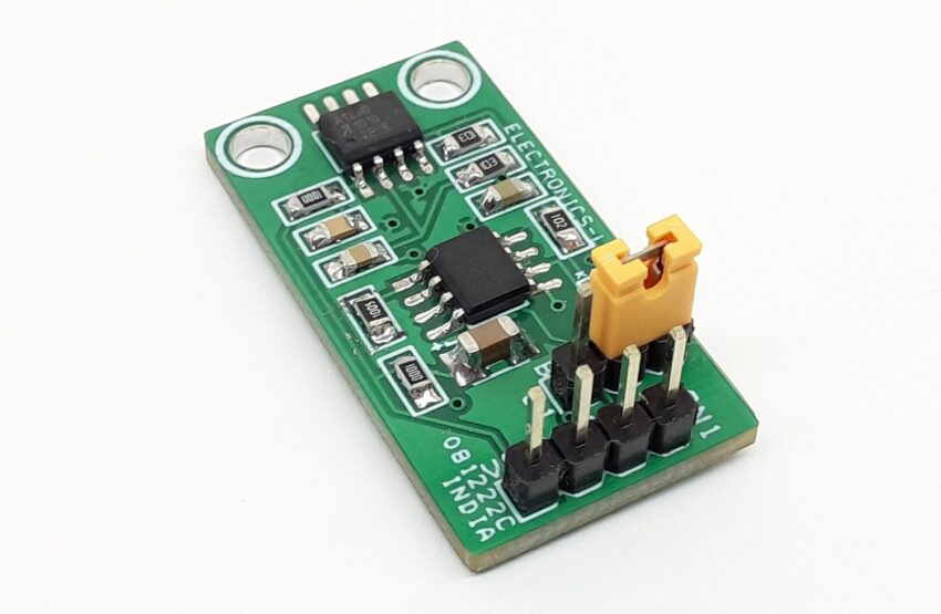
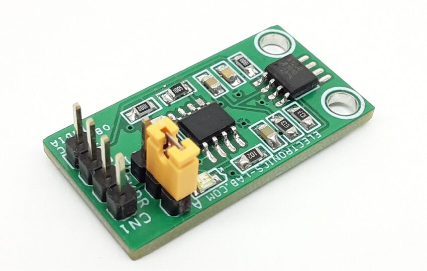
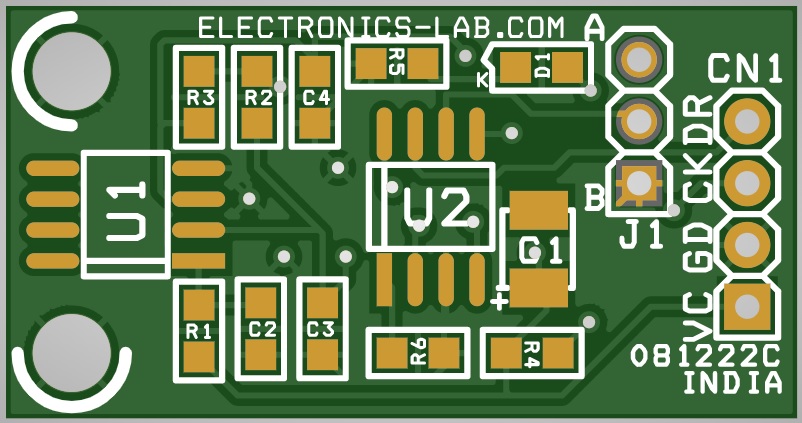
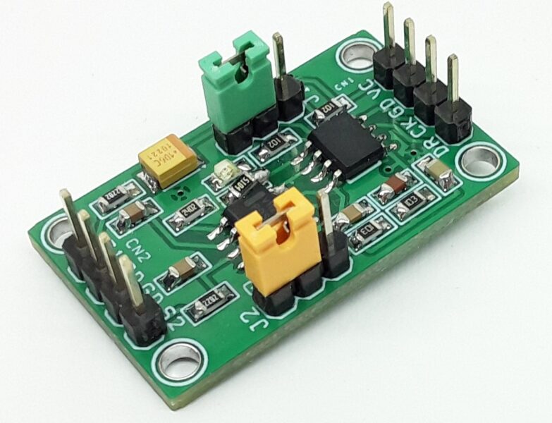
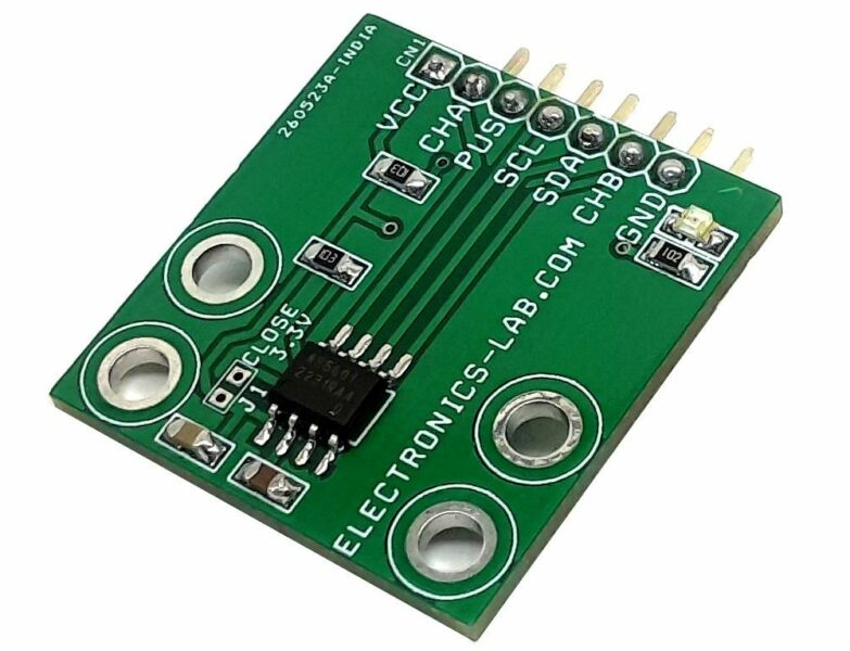
This is a highly sensitive, temperature-stable magnetic sensing module ideal for use in ring magnet-based, speed, and direction systems located in harsh automotive and industrial environments. The module is a complete solution to make a magnet-based rotary encoder, which provides clock and up/down direction signal output. The circuit consists of A1230 and LS7184 chips. A1230 is an ultra-sensitive dual-channel quadrature hall-effect bipolar switch, and LS7184 is a quadrature clock converter. A magnetic rotary encoder consists of 2 main components, a Magnetic disc, and a signal conditioner. The disc is magnetized with a number of poles around its circumference. The A1230 quadrature sensor detects the change in a magnetic field when the disc rotates and converts this information to two-channel rectangular pulses. Further, this quadrature signal is converted to a clock and up/down direction signal using the LS7184 chip. The resolution of the rotary encoder is determined by the number of magnetic poles around the disk and the output clock can be multiplied by factors of x1, x2, and x4 by changing the IC mode using jumper J1, thus this helps in increasing the output resolution.
Mode Selection Jumper J1
- Mode is a 3-state input to select resolution x1, x2, and x4. The input quadrature clock rate is multiplied by factors of 1,2 and 4 in x1, x2, and x4 modes respectively, thus producing a high-resolution output.
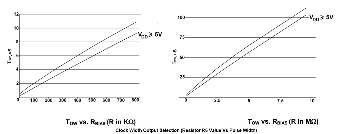
RBIAS Resistor 6 (Range 2K Ohm to 10M Ohms) – Refer to Figure
- The value of this resistor is responsible for the output clock pulse width. Alter the value to change the output pulse width. Please Refer to the datasheet for more info.
 Features
- Supply 5V DC
- Clock, UP/DOWN Direction Output
- 1 mm Hall element spacing
- Clock Can be Multiplied by Factors of x1, x2, and x4
- On Board Jumper for Clock Multiple Factor Setting for Higher Output Resolution
- 2 x 2.5 mm Mounting Holes
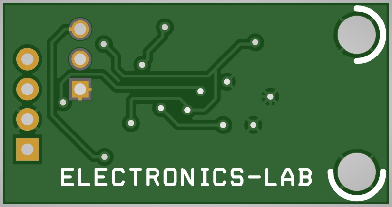
- PCB Dimensions 32.54 x 16.99 mm
Connections and Other Details
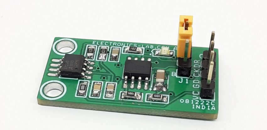
- CN1: Pin 1 = VCC 5V DC, Pin 2 = GND, Pin 3 = Clock Output, Pin 4 = Up/Down Direction Output
- Jumper J1: J1 Floating/Open = X4 , VCC = X2 , GND = X1 Factors Selection
- D1: Power LED
How do magnetic encoders work?
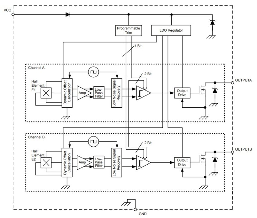
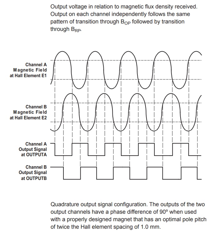
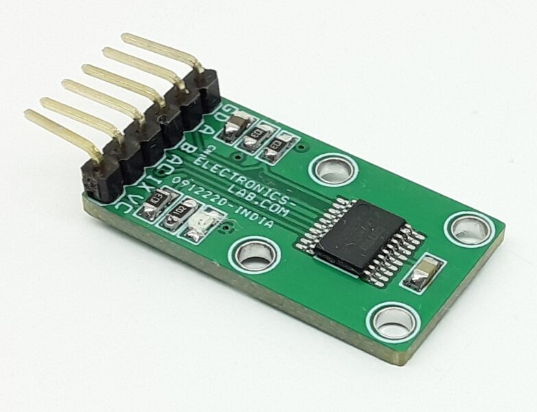
The A1230 is a dual-channel, bipolar switch with two Hall-effect sensing elements, each providing a separate digital output for speed and direction signal processing capability. The Hall elements are photolithographically aligned to better than 1 μm. Maintaining accurate mechanical location between the two active Hall elements eliminates the major manufacturing hurdle encountered in fine-pitch detection applications. The A1230 is a highly sensitive, temperature-stable magnetic sensing device ideal for use in ring magnet-based, speed and direction systems located in harsh automotive and industrial environments. For more details please visit: https://www.motioncontroltips.com/faq-how-do-magnetic-encoders-work/
Schematic
Parts List
| NO. | QNTY. | REF. | DESC | MANUFACTURER | SUPPLIER | SUPPLIER PART NO |
|---|---|---|---|---|---|---|
| 1 | 1 | CN1 | 4 PIN MALE HEADER PITCH 2.54MM | WURTH | 732-5317-ND | |
| 2 | 1 | C1 | 10uF/16V CERAMIC SMD SIZE 1210 | MURATA/YAGEO | ||
| 3 | 1 | C2 | 0.1uF/50V CERAMIC SMD SIZE 0805 | MURATA/YAGEO | ||
| 4 | 2 | C3,C4 | 10KPF/50V CERAMIC SMD SIZE 0805 | MURATA/YAGEO | ||
| 5 | 1 | D1 | RED LED SMD SIZE 0805 | OSRAM | 475-1278-1-ND | |
| 6 | 1 | J1 | JUMPER- 2PIN MALE HEADER PITCH 2.54MM | WURTH | 732-5315-ND | |
| 7 | 2 | R1,R4 | 100E 5% SMD SIZE 0805 | MURATA/YAGEO | ||
| 8 | 2 | R2,R3 | 10K 5% SMD SIZE 0805 | MURATA/YAGEO | ||
| 9 | 1 | R5 | 1K 5% SMD SIZE 0805 | MURATA/YAGEO | ||
| 10 | 1 | R6 | 8.2M 5% SMD SIZE 0805 | MURATA/YAGEO | ||
| 11 | 1 | U1 | A1230LLTR-T SOIC8 | ALLEGRO | 620-1348-1-ND | |
| 12 | 1 | U2 | LS7184 SOIC8 | lsicsi.com | ||
| 13 | 1 | J1 | SHUNT - JUMPER | SULLINS CONNECT | S9001-ND |
Connections
A1230 Block Diagram
LS7184 Block Diagram


