

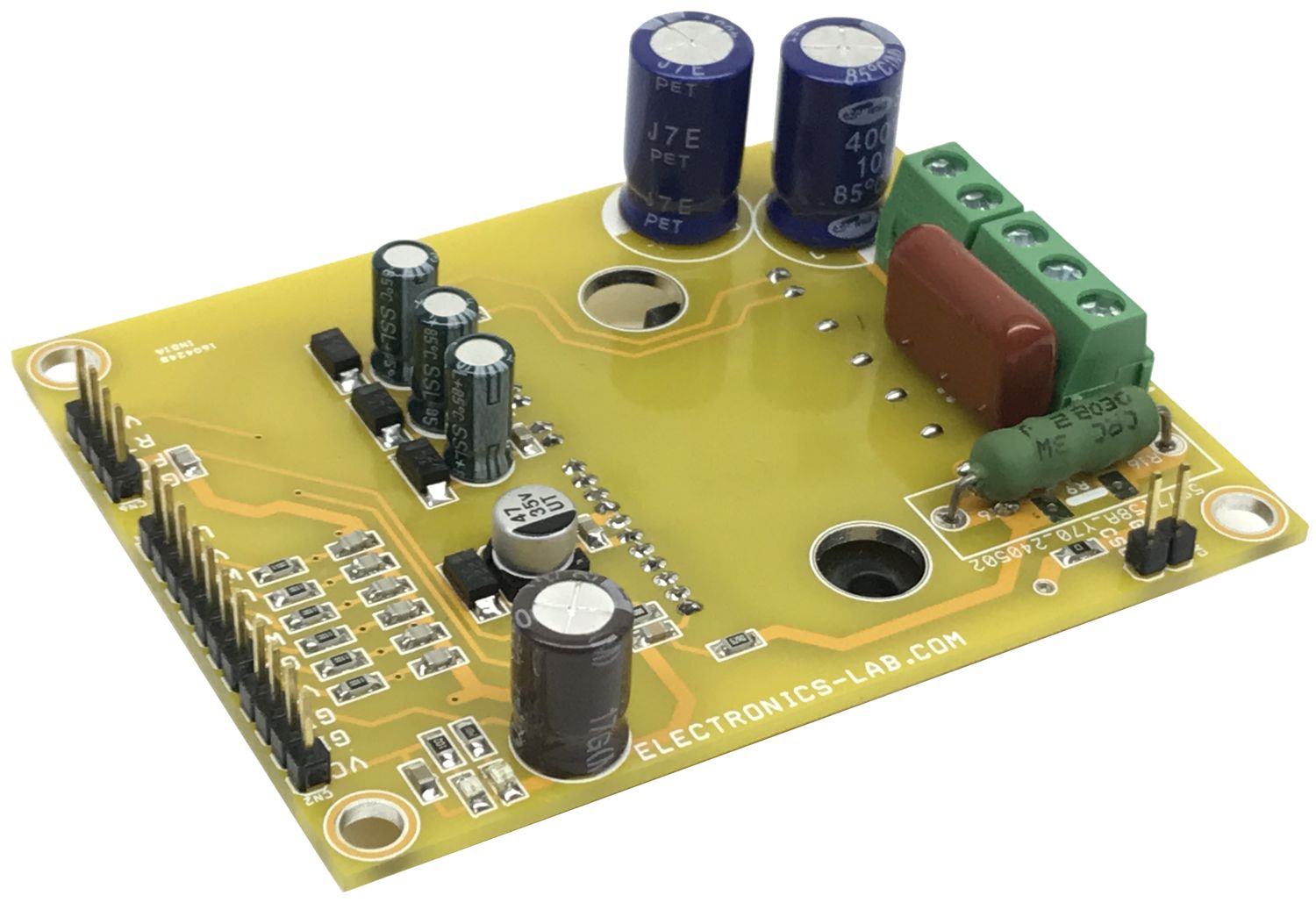
Smart Power Module for 3-Phase Motor – 5A
- Rajkumar Sharma
- 141 Views
- advanced
- Tested
- SKU: EL148557
- Quote Now
- 0 Likes

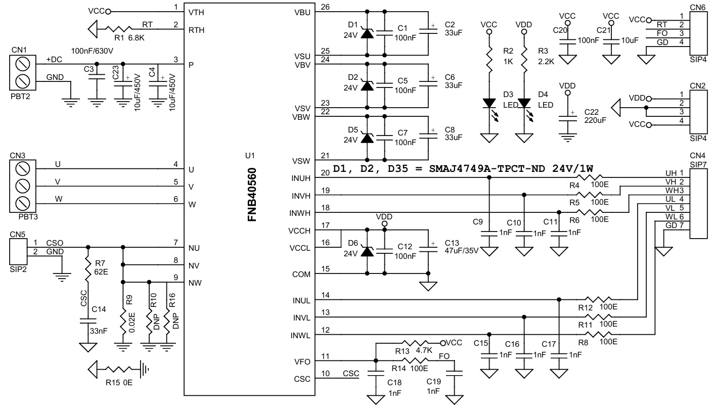
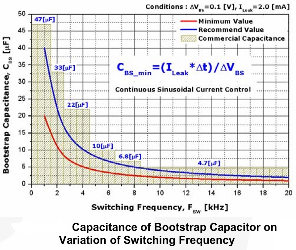
This is a Smart power module project designed for Small Power AC Motors. The FNB40560 chip is the heart of the project. A compact inverter project is ideal for small power motors such as fans and pumps. H-bridge configuration can also be created for low current high-voltage brushed DC motors. The Inverter project supports loads up to 5A. The DC power supply voltage is up to 400VDC. The project operates with 6 PWM signals. The parameters for bootstrap circuit elements are dependent on the PWM algorithm. For 5 kHz of switching frequency Bootstrap capacitors C2, C6, and C8 value is 33uF. Resistor R4, R5, R6, R12, R11, R8 and capacitor C9, C10, C11, C15, C16, C17 prevent improper signal due to surge-noise. ATS pin is provided to monitor the temperature of the IPM. A heatsink is needed for the IPM chip during operation or testing.
Note: The project operates with lethal voltage, user must take care of safety and all necessary precautions before testing the project.
Operation Truth Table
- HIN 0, LIN 0 = Output Z Both MOSFET Off
- HIN 0, LIN 1 = Output 0 Low Side MOSFET On
- HIN 1, LIN 0 = Output VDC High Side MOSFET On
- HIN 1, LIN 1 = Forbidden Shoot Through
Features
- Load Power Supply Up to 400V DC -+DC
- Load Current Continues 5A
- Logic Supply 15V DC (Gate Driver Circuit)-VDD
- Power Supply for Temperature sense Circuit 5V DC-VCC
- SCP, Over Current Trip Level 0.5V
- Input Frequency up to 20Khz (Choose Right Bootstrap Capacitor)
- Power Supply for Over Current Circuit (Comparator CN5) 5V DC
- One Board Power LED for Logic Supply
- Shunt Based Over Current Feedback Output
- HVIC for gate driving and under-voltage protection
- Active-High interface, can work with 3.3V/5V logic (PWM Signals)
- Optimized for low electromagnetic interference
- Isolation voltage rating of 1500Vrms for 1min
- 4 x 4mm Mounting Holes
- PCB Dimensions 79.85 x 62.39mm
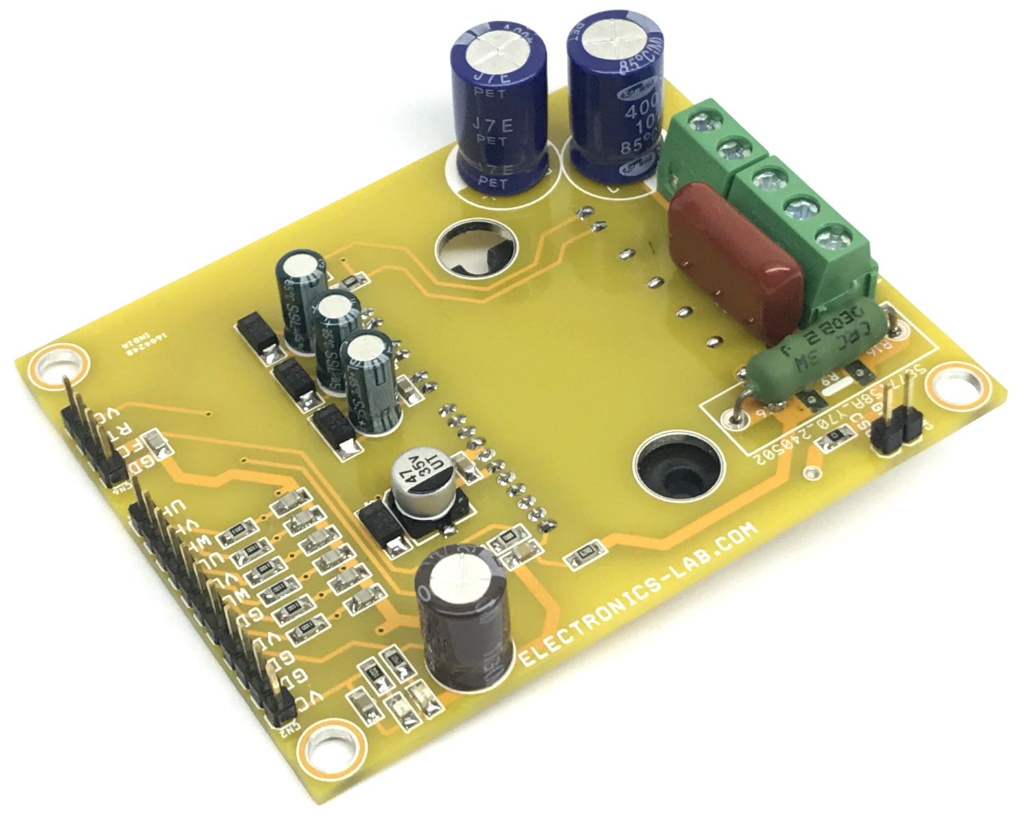
Signal Input Pins
- Pins: IN(UL), IN(VL), IN(WL), IN(UH), IN(VH), IN(WH)
- These pins control the operation of the MOSFETs.
- These pins are activated by voltage input signals. The terminals are internally connected to the Schmitt trigger circuit.
- The signal logic of these pins is active HIGH; the MOSFET turns ON when sufficient logic voltage is applied to the associated input pin.
- The wiring of each input needs to be short to protect the module against noise influences.
- An RC filter is used to mitigate signal oscillations or any noise that traces of input signals may pick up.
Current Sense Resistor (Board provided with dual type of current sense resistor SMD or THT)
- SMD 2512 Size 2 x Parallel Resistor
- THT Solder Resistor
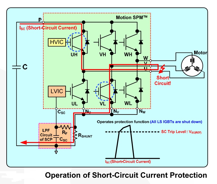
Short-Circuit Current Detection Pins
Pin: CSC
The current-sensing shunt resistor connected between the low-pass filter before the pin CSC and the low-side ground COM to detect short-circuit current
The shunt resistor should be selected to meet the detection levels matched for the specific application. An RC filter R7 and C14 connected to the CSC pin to eliminate noise. Connector CN5 provided for current feedback output, connector is connected across the shunt resistor. Refer Data sheet of IPM for more about trip voltage and shunt resistor.
Fault Output Pin (VFO)
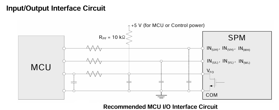
The VFO output is open-drain configured. The VFO signal line is pulled up to the 5V logic power supply with approximately 4.7kΩ resistance.
This is the fault output alarm pin. An active LOW output is given on this pin for a fault state condition in the SPM.
The alarmed conditions are SCP (Short-Circuit Current Protection) or low-side bias UVLO (Under Voltage Lockout) operation.
Bootstrap Capacitor, C2, C6, C8
Value of bootstrap capacitor is depended on input frequency, refer the figure Bootstrap Capacitor VS frequency for capacitor selection, also refer data sheet for more info.
Thermistor Bias Voltage
Pin: VTH
This is the bias voltage pin of the internal thermistor. It is connected to the 5V logic power supply. Series Resistor for the Use of Thermistor (Temperature Detection)
Pin: RTH
For case temperature (TC) detection, this pin connected to an external series resistor R1. Temperature feedback output is available CN6 pin 2.
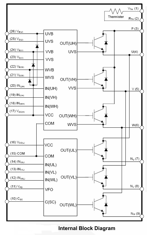
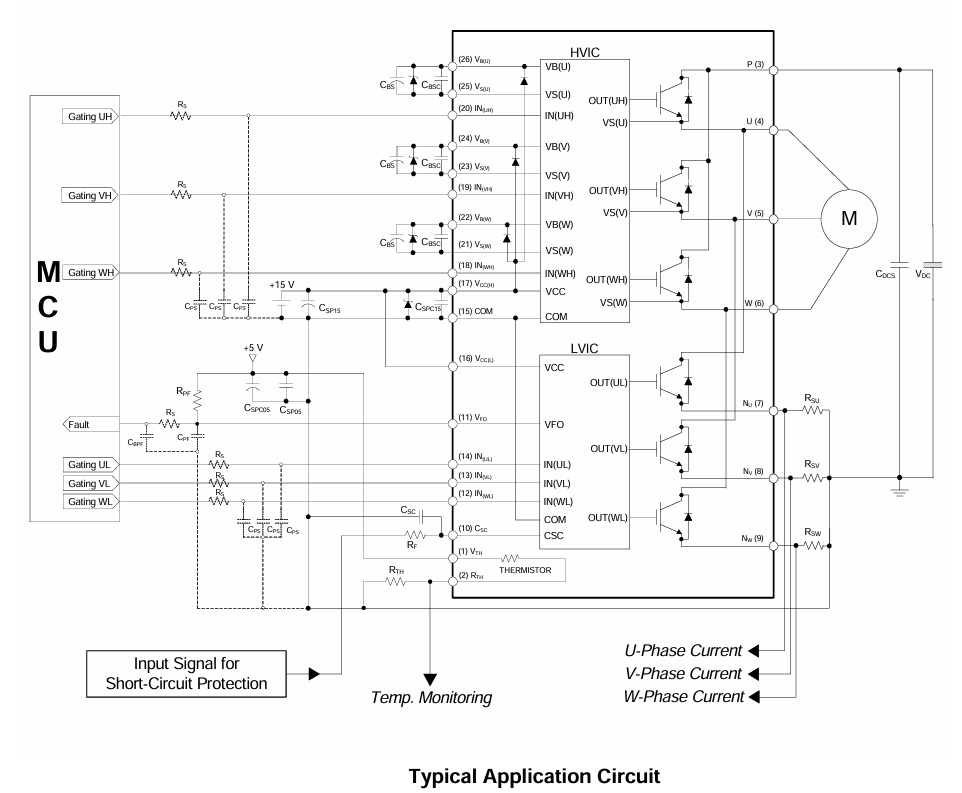
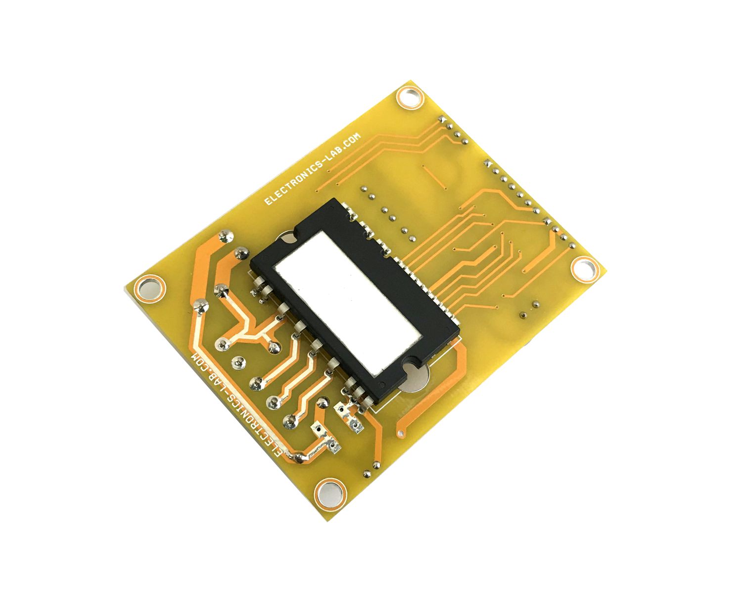
FNB40560 is a Motion SPM® 45 series that ON Semiconductor has newly developed to provide a very compact and high-performance inverter solution for AC motor drives in low-power applications such as refrigerators and dish washers. It combines low-loss short-circuit rated IGBTs and optimized gate drivers in a fully isolated package to deliver a simple and robust design. The system reliability is further enhanced by the built-in NTC for temperature monitoring, integrated under-voltage lock-out function for both high and low side, and an over-current protection input. Three separate open-emitter pins for low side IGBTs make three leg current sensing possible. Built-in bootstrap diodes and dedicated VS pins make PCB layout easy.
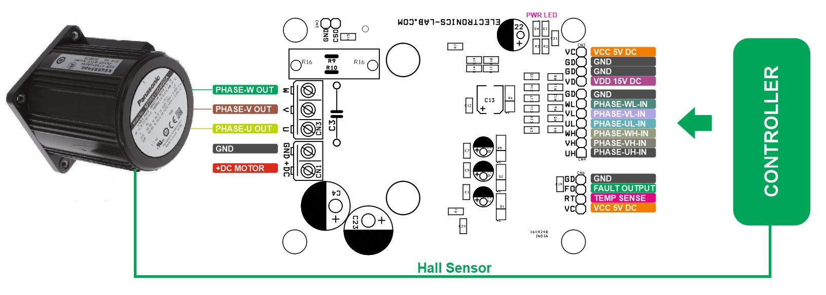
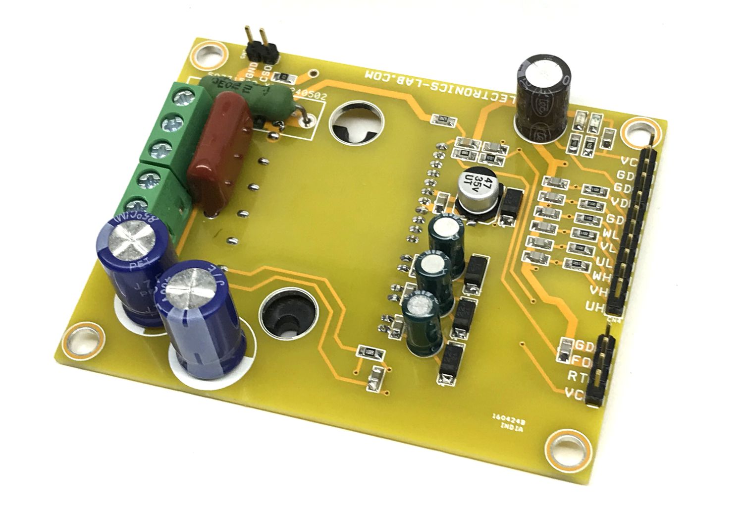
Connections
- CN1: Pin 1 +DC Motor Power Supply up to 400V DC, Pin 2 = GND
- CN2: Pin 1 15V DC for Logic Gate Driver, Pin 2 GND, Pin 3 = GND, Pin 4 = VCC 5V DC for Temperature Sensor
- CN3: Pin 1 = Motor Phase U, Pin 2 = Motor Phase V, Pin 3 = Motor Phase W
- CN4: Pin 1 = PWM=High Input Phase-U, Pin 2 = PWM-High Input Phase-V, Pin 3 = PWM-High Input Phase-W, Pin 4 = PWM=Low Input Phase-U, Pin 5 = PWM=Low Input Phase-V, Pin 6 = PWM=Low Input Phase-W, Pin 7 = GND
- CN5: Pin 1 = Current Sense Output Pin 1, Pin 2 = GND
- CN6: Pin 1 = VCC 5V DC, Pin 2 Temp Sensor, Pin 3 = Fault Output, Pin 4 = GND
- D3: 5V Power LED
- D4: 15V Power LED
Schematic
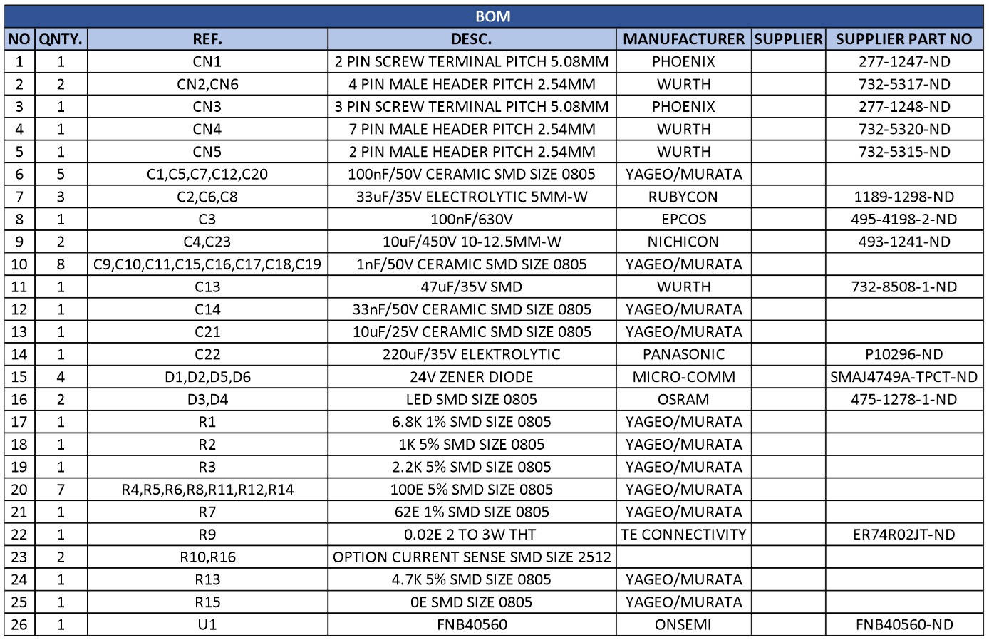
Parts List
| NO | QNTY. | REF. | DESC. | MANUFACTURER | SUPPLIER | SUPPLIER PART NO |
|---|---|---|---|---|---|---|
| 1 | 1 | CN1 | 2 PIN SCREW TERMINAL PITCH 5.08MM | PHOENIX | 277-1247-ND | |
| 2 | 2 | CN2,CN6 | 4 PIN MALE HEADER PITCH 2.54MM | WURTH | 732-5317-ND | |
| 3 | 1 | CN3 | 3 PIN SCREW TERMINAL PITCH 5.08MM | PHOENIX | 277-1248-ND | |
| 4 | 1 | CN4 | 7 PIN MALE HEADER PITCH 2.54MM | WURTH | 732-5320-ND | |
| 5 | 1 | CN5 | 2 PIN MALE HEADER PITCH 2.54MM | WURTH | 732-5315-ND | |
| 6 | 5 | C1,C5,C7,C12,C20 | 100nF/50V CERAMIC SMD SIZE 0805 | YAGEO/MURATA | ||
| 7 | 3 | C2,C6,C8 | 33uF/35V ELECTROLYTIC 5MM-W | RUBYCON | 1189-1298-ND | |
| 8 | 1 | C3 | 100nF/630V | EPCOS | 495-4198-2-ND | |
| 9 | 2 | C4,C23 | 10uF/450V 10-12.5MM-W | NICHICON | 493-1241-ND | |
| 10 | 8 | C9,C10,C11,C15,C16,C17,C18,C19 | 1nF/50V CERAMIC SMD SIZE 0805 | YAGEO/MURATA | ||
| 11 | 1 | C13 | 47uF/35V SMD | WURTH | 732-8508-1-ND | |
| 12 | 1 | C14 | 33nF/50V CERAMIC SMD SIZE 0805 | YAGEO/MURATA | ||
| 13 | 1 | C21 | 10uF/25V CERAMIC SMD SIZE 0805 | YAGEO/MURATA | ||
| 14 | 1 | C22 | 220uF/35V ELEKTROLYTIC | PANASONIC | P10296-ND | |
| 15 | 4 | D1,D2,D5,D6 | 24V ZENER DIODE | MICRO-COMM | SMAJ4749A-TPCT-ND | |
| 16 | 2 | D3,D4 | LED SMD SIZE 0805 | OSRAM | 475-1278-1-ND | |
| 17 | 1 | R1 | 6.8K 1% SMD SIZE 0805 | YAGEO/MURATA | ||
| 18 | 1 | R2 | 1K 5% SMD SIZE 0805 | YAGEO/MURATA | ||
| 19 | 1 | R3 | 2.2K 5% SMD SIZE 0805 | YAGEO/MURATA | ||
| 20 | 7 | R4,R5,R6,R8,R11,R12,R14 | 100E 5% SMD SIZE 0805 | YAGEO/MURATA | ||
| 21 | 1 | R7 | 62E 1% SMD SIZE 0805 | YAGEO/MURATA | ||
| 22 | 1 | R9 | 0.02E 2 TO 3W THT | TE CONNECTIVITY | ER74R02JT-ND | |
| 23 | 2 | R10,R16 | OPTION CURRENT SENSE SMD SIZE 2512 | |||
| 24 | 1 | R13 | 4.7K 5% SMD SIZE 0805 | YAGEO/MURATA | ||
| 25 | 1 | R15 | 0E SMD SIZE 0805 | YAGEO/MURATA | ||
| 26 | 1 | U1 | FNB40560 | ONSEMI | FNB40560-ND |
Connections
Block Diagram
Typical Application
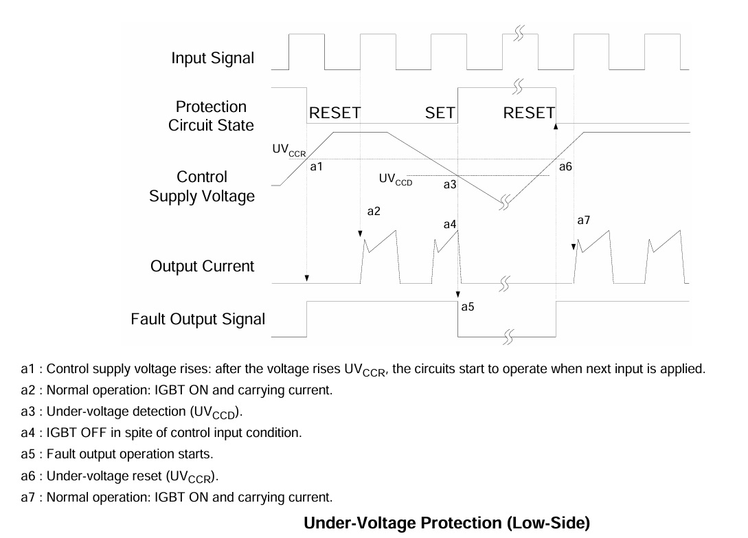
Undervoltage Protection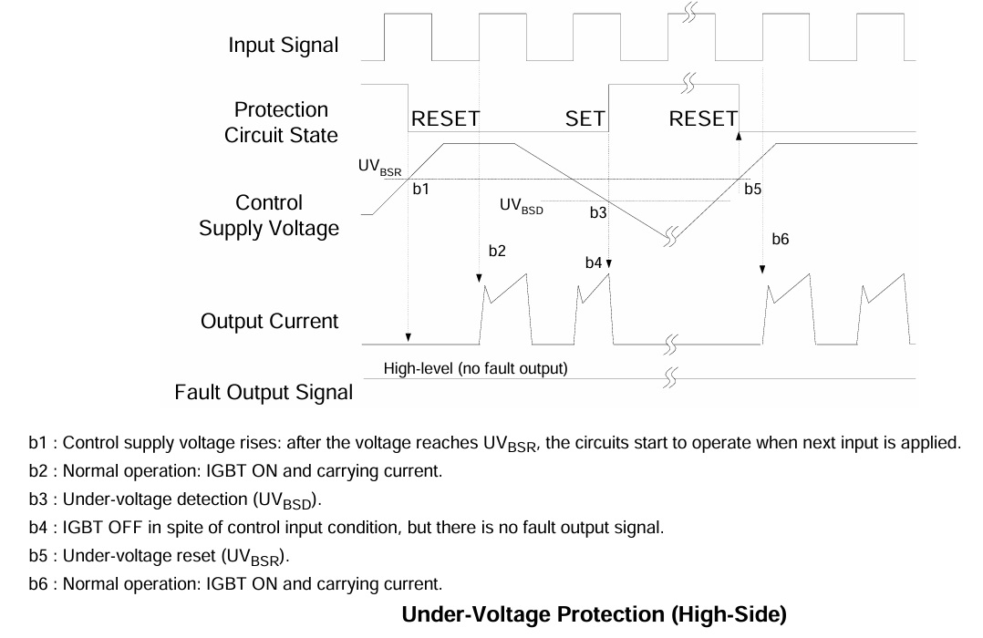
MCU Interface
Temperature Curve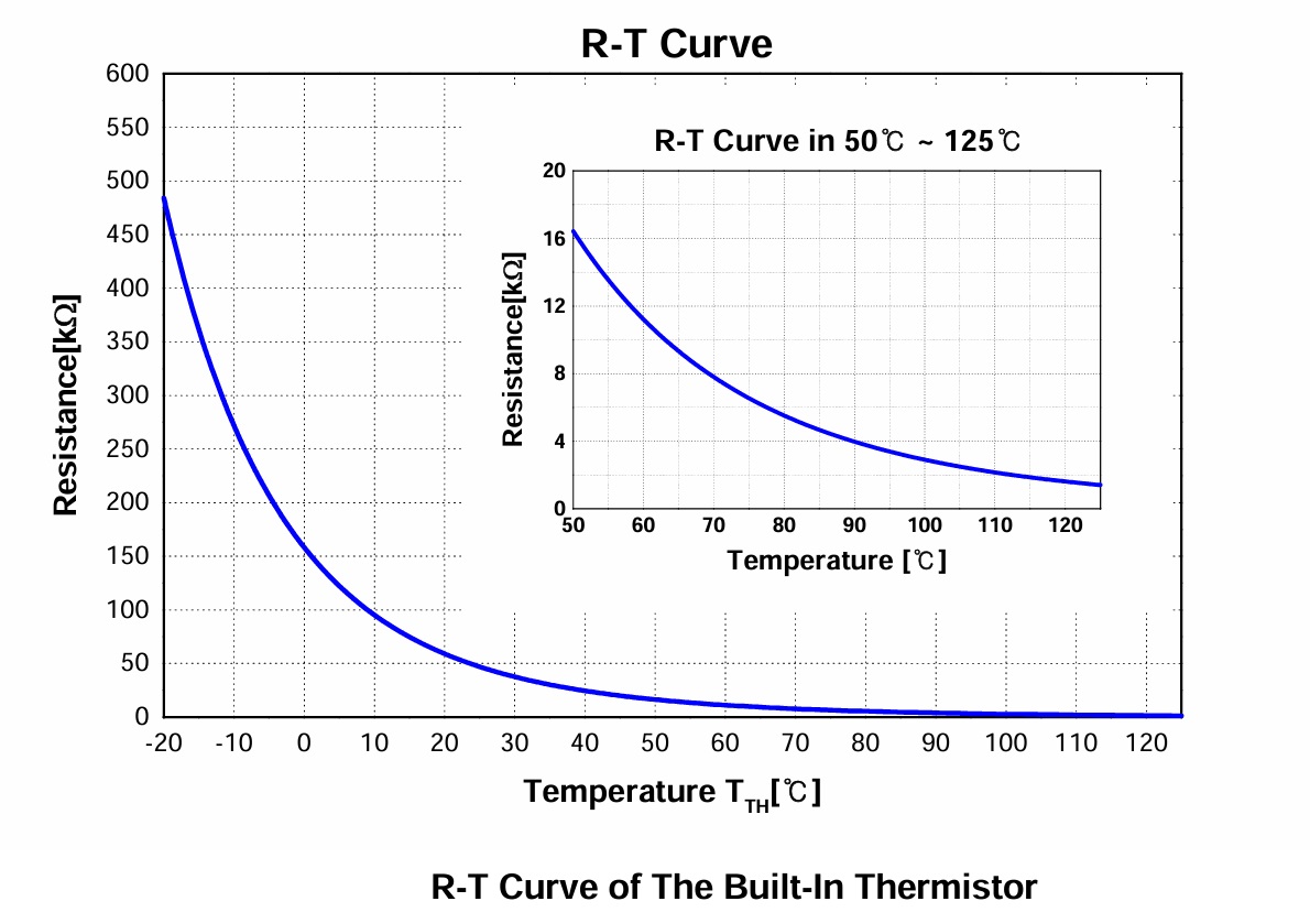
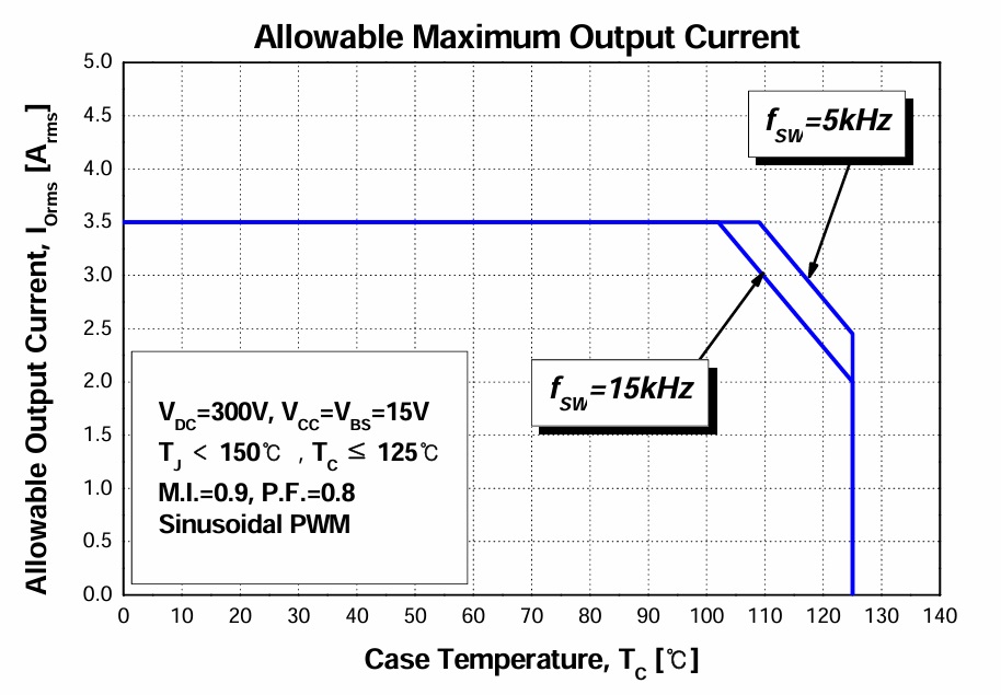
Maximum Output Current
Short Circuit Protection Diagram
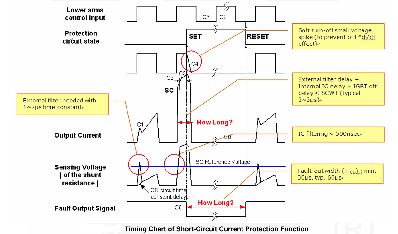
Timing Diagram
Bootstrap Capacitor vs Frequency
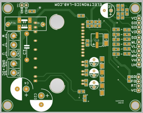
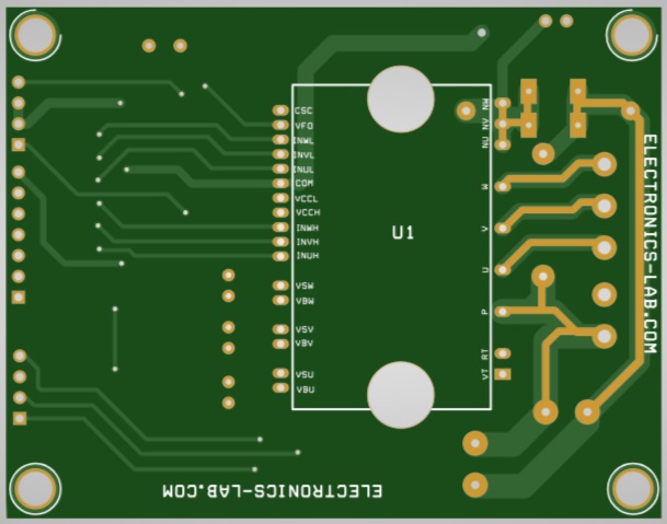
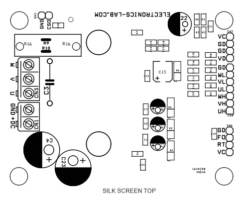
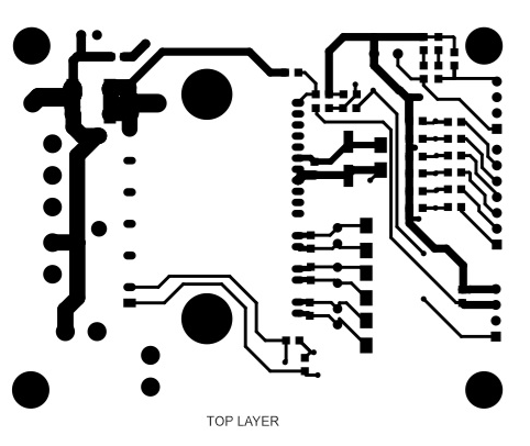
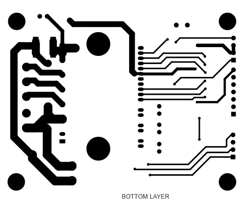
Gerber View
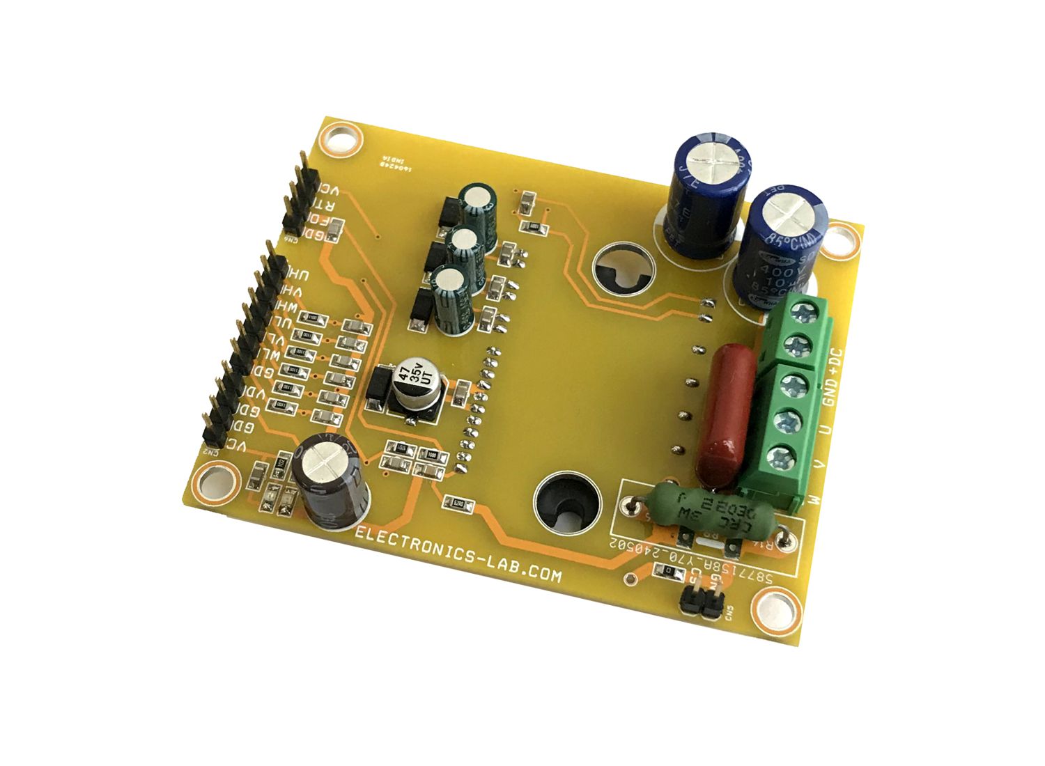
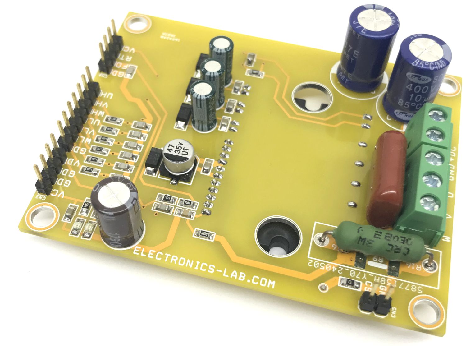
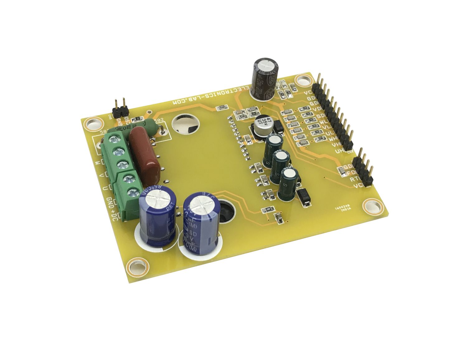
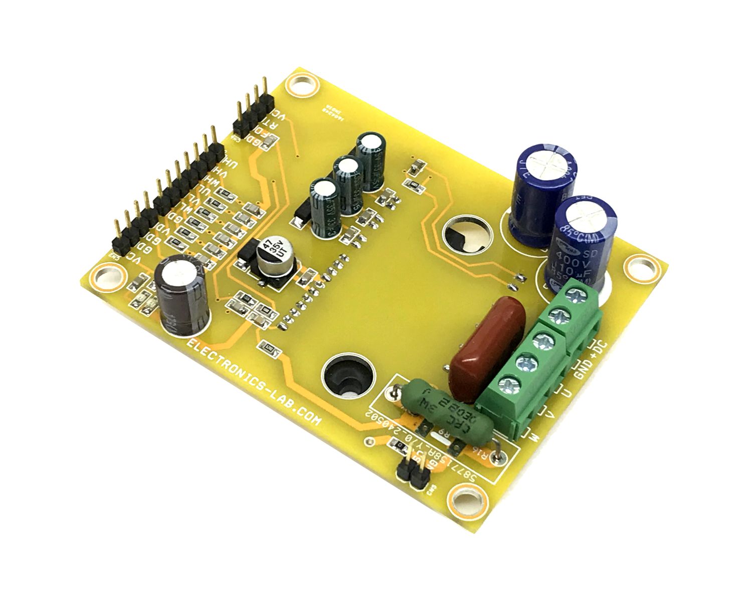
Photos
Video
FNB40560 Datasheet
Please follow and like us:
PCB


Subscribe
Login
0 Comments


