Sound to RC Servo Driver
- Rajkumar Sharma
- 16.209 Views
- easy
- Tested
- SKU: EL66703
- Quote Now
New Version: A new version of the Sound to RC Servo is available “Sound to RC Servo Driver v2.0 – Arduino Compatible”
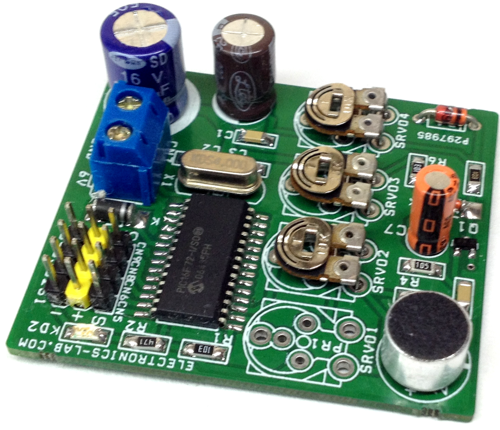
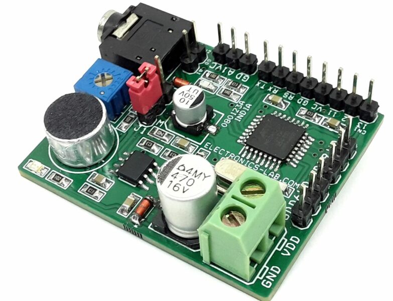
This project is designed for Animatronics and Puppeteer applications, however, it can be used in other applications like sound-responsive toys, robots, etc. Especially this project helps to move the jaw or mouth of an animatronic creature.
The project moves the RC-servo once receives any kind of sound. The rotation angle depends on the sound level, the more the sound level more the movement. The movement of the servo is proportional to the sound level.
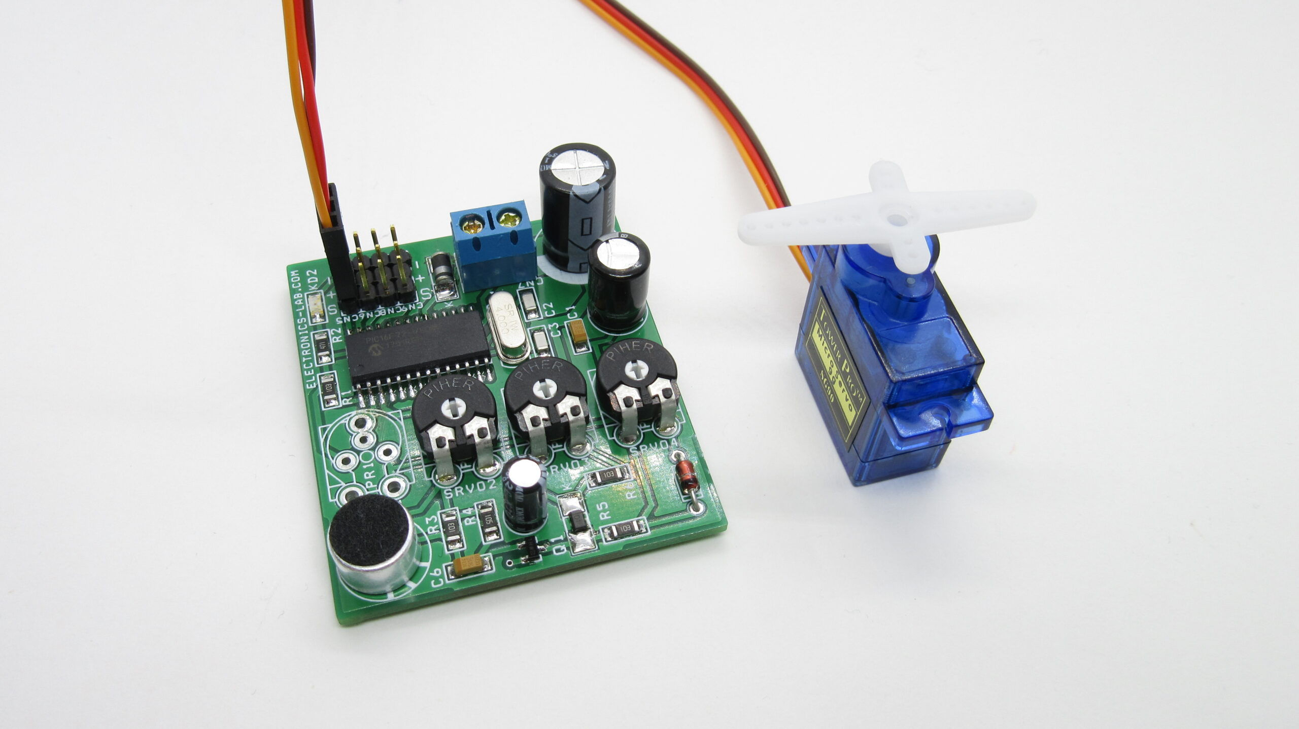
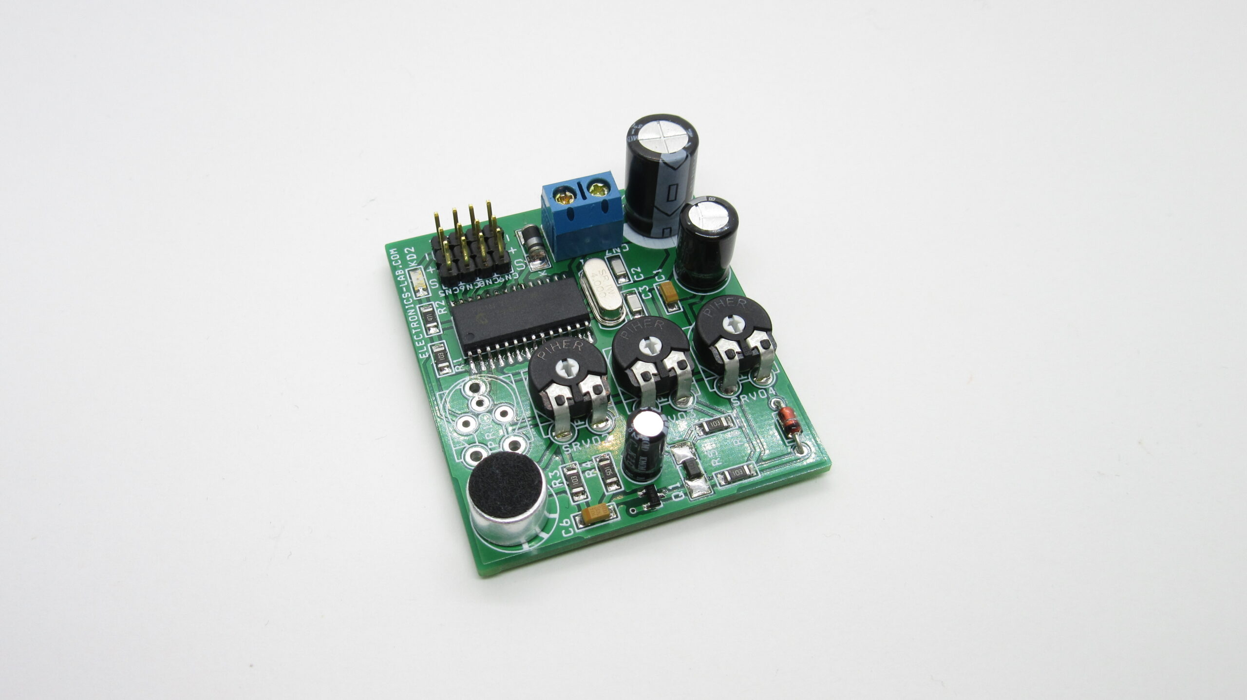
The circuit has 4 channel servo drivers, the First channel is driven by sound, and the rest 3 RC servos are controlled by the onboard trimmer potentiometer, these 3 channels help to drive other movements of the animatronics figure.
Sound Received by the microphone is converted to DC voltage, PIC16F72 microcontroller converts DC voltage into the RC PWM signal. The circuit works with 5V DC and it is advisable to use a battery for low jitter.
Features
- Supply 5V to 6V DC (1.5V X 4 AA or Large 6V SLA Battery)
- 4 Channel RC Servo Drivers
- 1St Channel works with Sound
- 3 Channel works with an onboard potentiometer
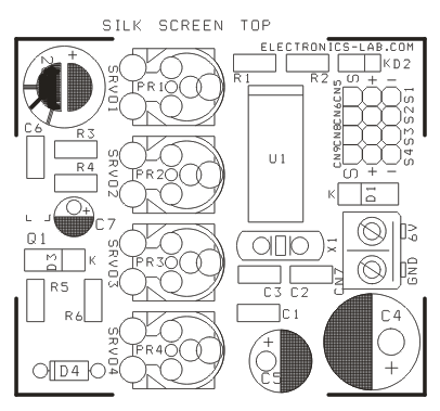
- CN7 Supply
- D2 Power LED
- CN6, CN8, and CN9 Connectors for RC Servo work with Potentiometer
- Trimmer Potentiometer PR2= SERVO 2, PR3=SERVO 3, PR4=SERVO4
- CN5 Connector for RC Servo works with Sound
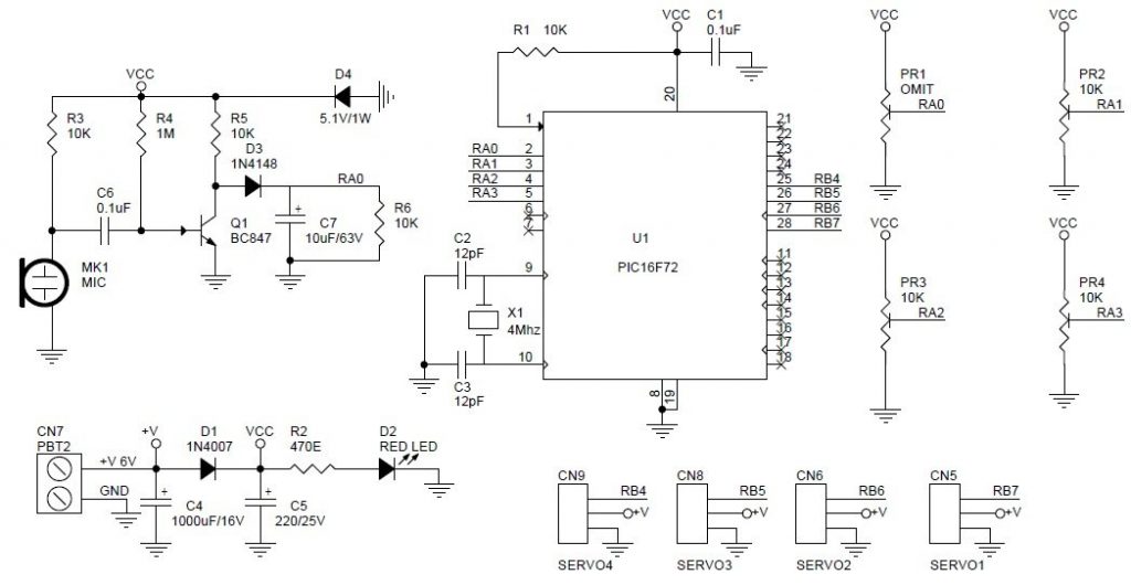
Schematic with MIC input
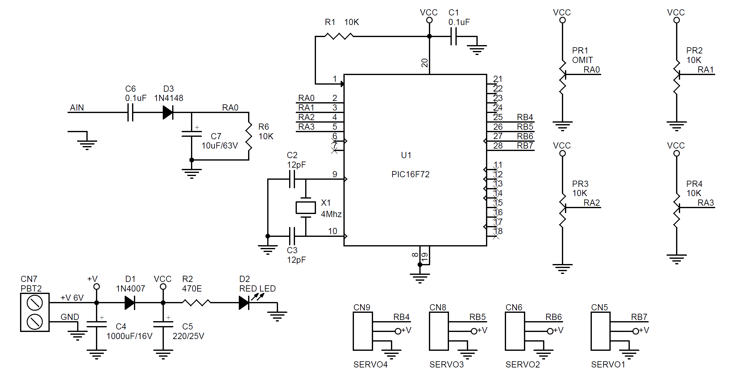
Schematic with Analog Audio input
Parts List
| SR. | QNTY. | REF. | DESC | LCSC.com | MOUSER.com |
|---|---|---|---|---|---|
| 1 | 4 | CN5,CN6,CN8,CN9 | 3 PIN HEADER CONNECTOR 2.54 MM PITCH | C492403 | |
| 2 | 1 | CN7 | 2 PIN SCREW TERMINAL 5.08MM PITCH | C91153 | |
| 3 | 2 | C1,C6 | 0.1uF SMD 1206 | C313097 | |
| 4 | 2 | C2,C3 | 12pF/50V SMD SIZE 1206 | C113882 | |
| 5 | 1 | C4 | 1000uF/16V ELECTROLYTIC | C357639 | |
| 6 | 1 | C5 | 220uF/25V ELECTROLYTIC | C106732 | |
| 7 | 1 | C7 | 10uF/63V ELECTROLYTIC | C216300 | |
| 8 | 1 | D1 | 1N4007 SMD SM4007 | C727082 | |
| 9 | 1 | D2 | RED LED SMD SIZE 1206 | C192674 | |
| 10 | 1 | D3 | 1N4148 SMD | C2828417 | |
| 11 | 1 | D4 | 5.1V/1W | C41431 | |
| 12 | 1 | MK1 | CONDENSOR MICROPHONE | C234028 | |
| 13 | 1 | PR1 | OMIT | # | # |
| 14 | 3 | PR2,PR3,PR4 | 10K TRIMMER POT - PT10LV10-103A2020 | 531-PT10LV113A22PMS | |
| 15 | 1 | Q1 | BC847 SMD | C181140 | |
| 16 | 1 | R2 | 470E SMD 1206 | C269761 | |
| 17 | 1 | R4 | 1M SMD 1206 | C115422 | |
| 18 | 1 | U1 | PIC16F72-I/SO SMD | 579-PIC16F72-I/SO | |
| 19 | 1 | X1 | 4Mhz CRYSTAL | C240919 | |
| 20 | 4 | R1, R3,R5,R6 | 10K SMD 1206 | C118075 |
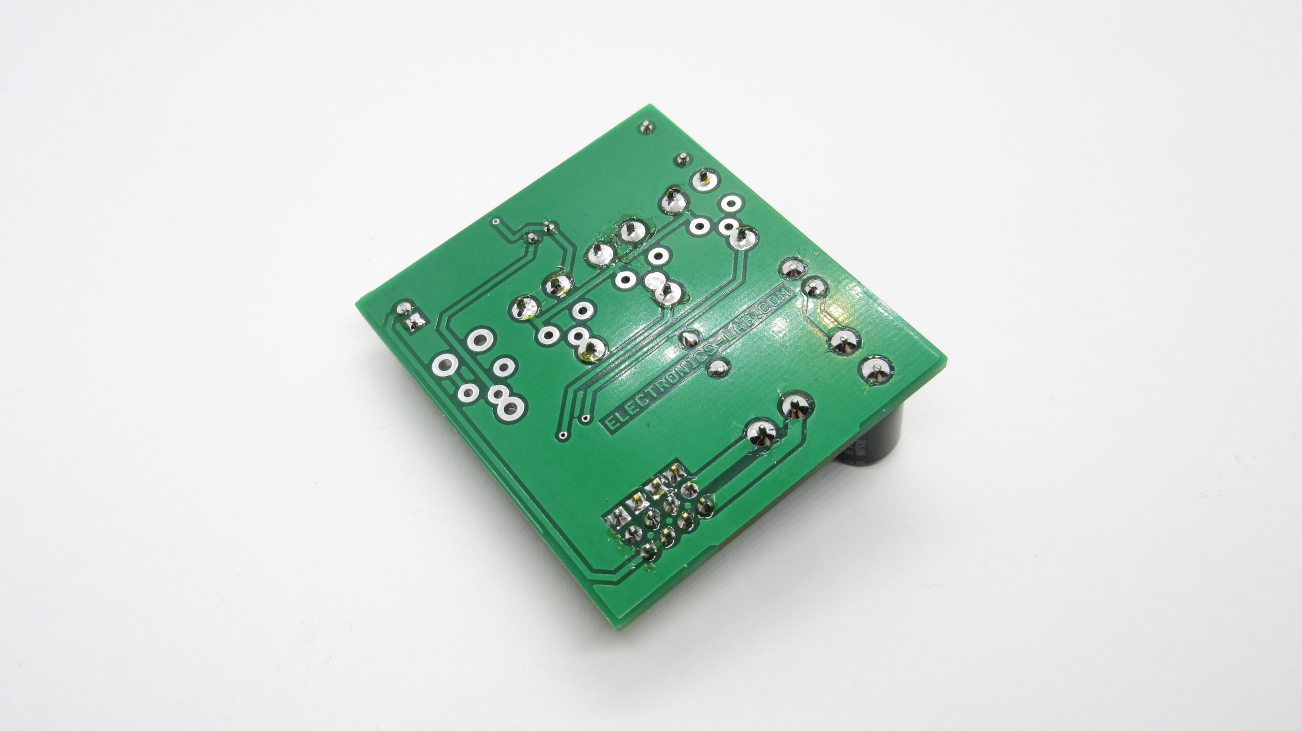
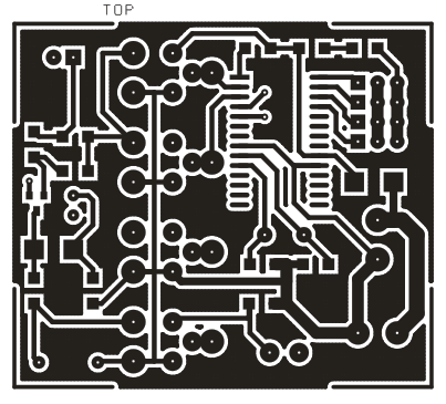
Photos
Video
Customer Applications




Hi there, Thank you for the information. Where can I get this board? Is sold somewhere?
Hi, it is not sold, but we can manufacture it for you if order is >25 pieces. If you are interested use the contact us form.
Yes let me know the cost for 24 pieces
can you still produce these boards?
Yes, we can produce this in order. Please contact us from the contact-us section of the website.
Will this board work with an external input. Say direct input from a sound source like a 3.5mm jack playing a voice? Also, correct me if I’m wrong but the other 3 channels could be used if say you have a mouth using 2 servo’s (one on each side of jaw) …Am I correct? Let me know as we would be willing to build one..just need to understand a bit more.
Wish they would had replied because I too am curious
Hi how much to have 25 of these units to be made.
check your email.
Hi, I am interested in buying 2 or 3 of these boards . Can you please tell me a price ?
check your email, please!
Hi, I am interested in buying one of these boards. can you tell me a price
How much would it cost to buy 5 of these boards (pre-assembled and ready o go?)
check your email, please!
Do you also happen to have the CPL file for this?
What do you mean with CPL file ?
Hello, can someone help lease. i’ve created the cicuit it turns etc. but do not work. no reaction to sound or movement usin potentiometer.
Have you programmed the MCU successfully?
Hi, I just recieved the assembled board. Super fast shipping and it works fantastic with the in-built mic. My final project will need the analog input, and I am not sure on how to do the mod. the info on this page with the schematics is very detailed, but being a complete beginner they don’t really make much sense to me unfortunately. Could you provide more instruction or perhaps a picture of the board in the analog input configuration? Thank you so much in advance.
do you sell just the pic chip????
Sorry, this is not available as a single chip.
Do you sell this completely assembled if so how much? Does it run on ac or dc?
Yes, it’s assembled, programmed, and tested, It runs on DC.
I’m trying to understand the audio in circuit. It looks like you filter DC, then rectify, then smooth. Is this just to get a smoother version of the input signal? I’m guessing the smoothing capacitor is not large enough to completely smooth things back to DC. Is this right? Thanks.
hi. i want to order this pcb board plz email cost
This is available assembled here: https://www.electronics-lab.com/product/sound-to-rc-servo-driver/
If you need only the PCB I can take a look for a spare one.
Hi, I was wondering if your could clarify the steps to remove the mic and attach a direct line to this board.
You have listed:
“if you want to drive the input with a direct audio signal remove R3 (10K) and microphone and feed audio to C6”
Does this mean to unsolder the mic and the chip R3 from the board and solder line in connection to C6 chip?
is there a possibilty to have the source code , i do have a bunch of mix pic micro , but not the 16f72 or can i use
another pic using the hex
thanks in adance
Unfortunately, the source code is not available right now.
How can I modify the circuit to install a more powerful servo at 8 or 12 volts?
bought two of these boards from you
everything works well
but there was a need to install a more powerful servo drive
please give advice
Is this possible in principle?
for example, part of the circuit operates at a voltage of 8 volts, and that part of the circuit where the board has a voltage of 6 volts.
will this work?
You may try to power the servo out of the circuit, connecting Vcc of servo pin with 8V, while keeping the PWM signal, and use common ground.