Stereo Audio Digital-to-Analog Converter Module
- Rajkumar Sharma
- 106 Views
- medium
- Tested
- SKU: EL154188
- Quote Now
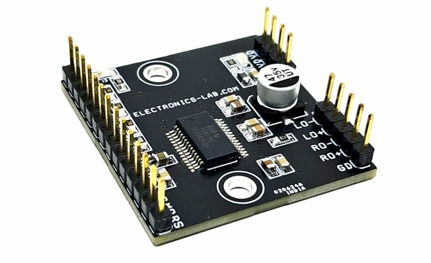
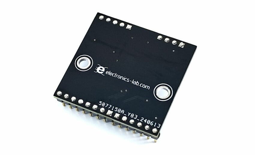
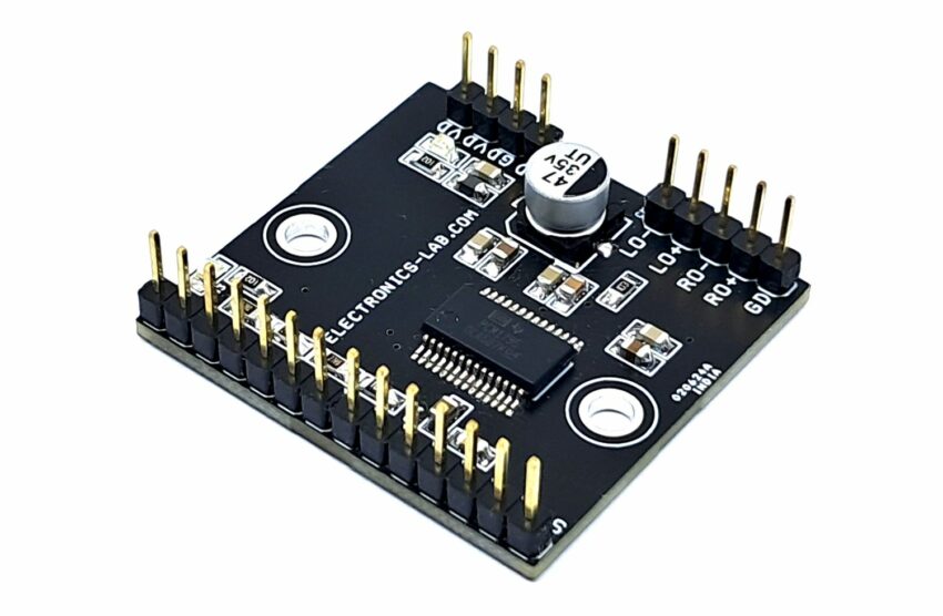
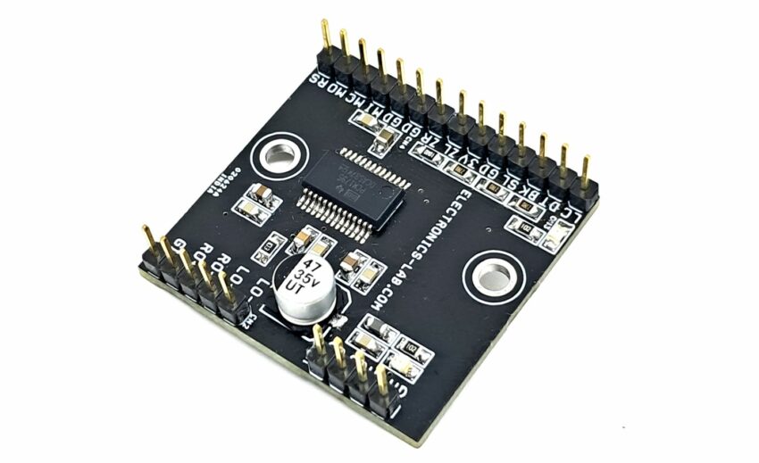
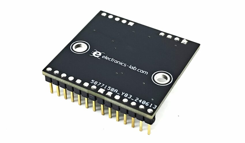
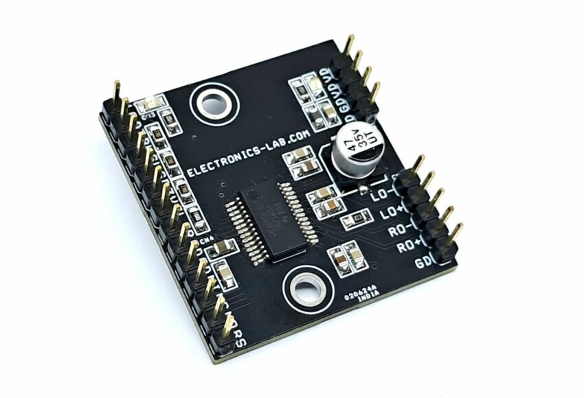
This is a breakout board for the IC PCM1795 stereo digital-to-analog converter (DAC), The DAC module accepts pulse code modulation (PCM) and direct stream digital (DSD) audio data formats, thus providing an easy interface to audio digital signal processors (DSPs) and decoder chips which will convert digital signal into analog signal. Sampling rates up to 200 kHz are supported. A full set of user-programmable functions is accessible through an SPI or I2C serial control port that supports register write and readback functions. The PCM1795 device supports the time-division-multiplexed (TDM) command and audio (TDMCA) data format.
Features
- Dual Supply Operations 5V for Analog and 3.3V for Digital
- 32-Bit Resolution
- Analog Performance:
- Dynamic Range: 123 dB
- THD+N: 0.0005%
- Differential Current Output: 3.9 mAPP
- 8× Oversampling Digital Filter:
- Stop-Band Attenuation: –98 dB
- Passband Ripple: ±0.0002 dB
- Sampling Frequency: 10 kHz to 200 kHz
- System Clock: 128, 192, 256, 384, 512, or 768 fS With Autodetect
- Accepts 16-, 24-, and 32-Bit Audio Data
- PCM Data Formats: Standard, I2S, and Left- Justified
- DSD Format Interface Available
- Interface Available for Optional External Digital Filter or DSP
- TDMCA or Serial Port (SPI™/I2C)
- User-Programmable Mode Controls:
- Digital Attenuation:
- 0 dB to –120 dB, 0.5-dB/Step
- Digital De-Emphasis
- Digital Filter Roll-Off: Sharp or Slow
- Soft Mute
- Zero Flag for Each Output
- Dual Supply Operation:
- 5-V Analog, 3.3-V Digital
- 5-V Tolerant Digital Inputs
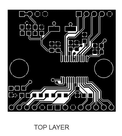
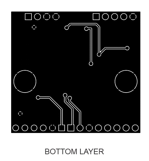
- PCB Dimensions 36.04 x 33.97 mm
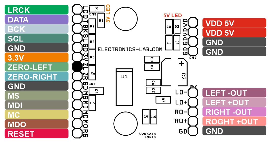
Connections
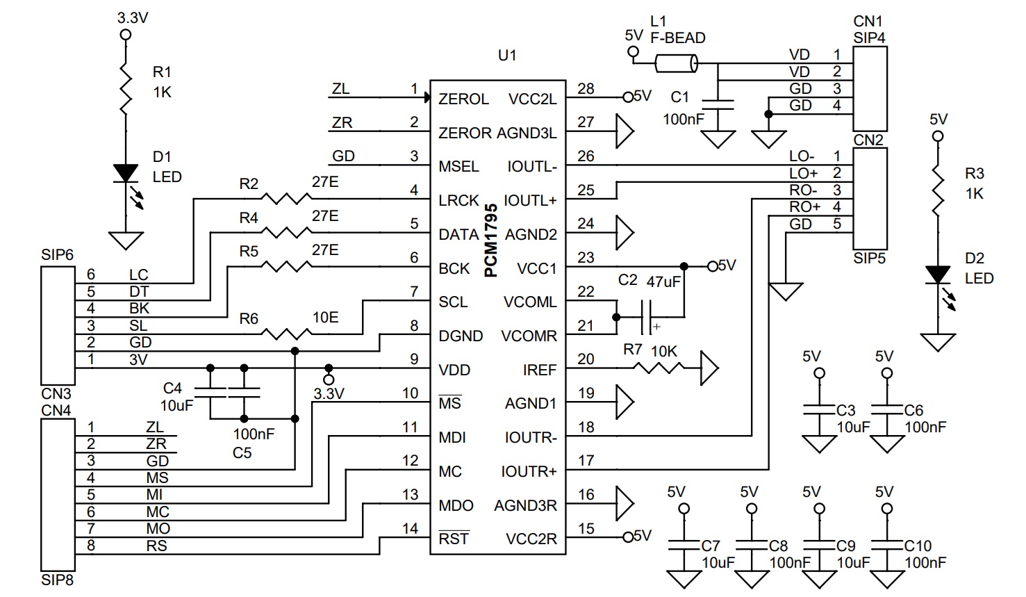
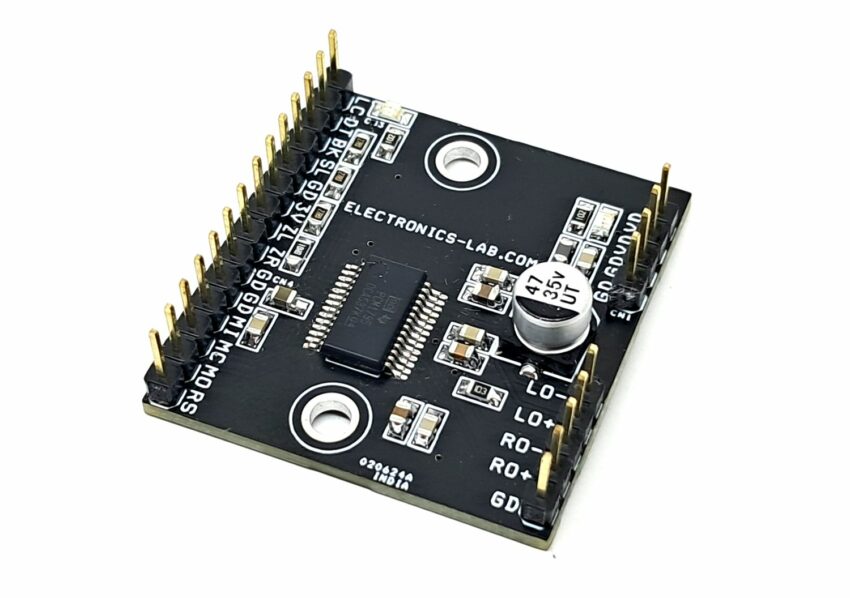
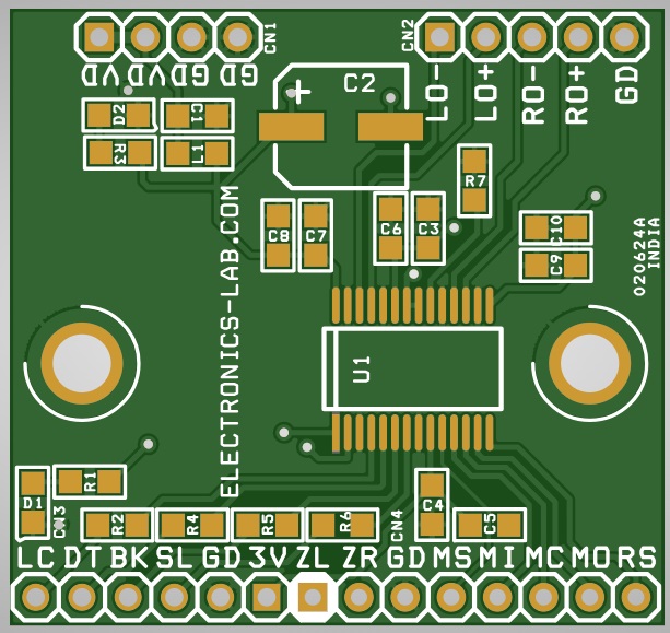
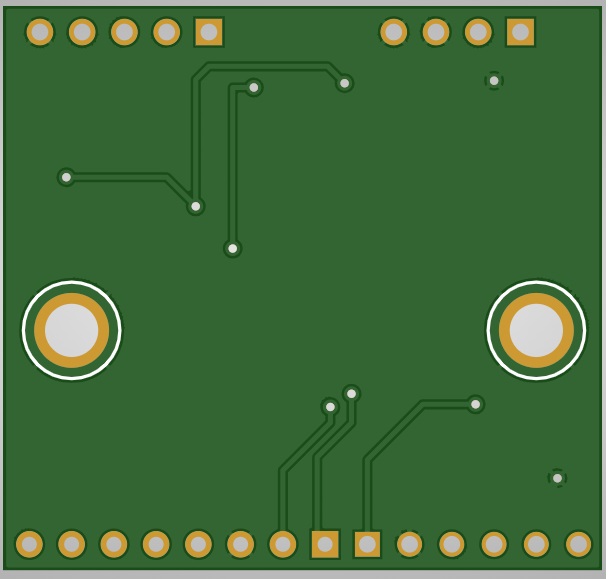
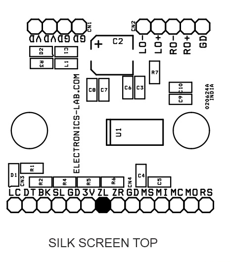
- CN1: Pin 1,2 = VD-5V , Pin 3,4=GND
- CN2: Audio/I Output Pin 1 = Left -Out, Pin 2 = Left +Out, Pin 3 = Right -Out, Pin 4 = Right +out. Pin 5 = GND
- CN3: Pin 1 = 3.3V , Pin 2 = GND, Pin 3 = SCL, Pin 4 = BCK, Pin 5 = Data, Pin 6 = LRCK
- CN4: Pin 1 = ZEROL, Pin 2 ZEROR, Pin 3 = GND, Pin 4 = MS, Pin 5 = MDI, Pin 6 = MC, Pin 7 = MDO, Pin 8 = RESET
- D1: 3.3V Power LED
- D2: 5V Power LED
Schematic
Parts List
| NO | QNTY | REF | DESC. | MANUFACTURER | SUPPLIER | SUPPLIER PART NO |
|---|---|---|---|---|---|---|
| 1 | 1 | CN1 | 4 PIN MALE HEADER PITCH 2.54MM | WURTH | DIGIKEY | 732-5317-ND |
| 2 | 1 | CN2 | 5 PIN MALE HEADER PITCH 2.54MM | WURTH | DIGIKEY | 732-5318-ND |
| 3 | 1 | CN3 | 6 PIN MALE HEADER PITCH 2.54MM | WURTH | DIGIKEY | 732-5319-ND |
| 4 | 1 | CN4 | 8 PIN MALE HEADER PITCH 2.54MM | WURTH | DIGIKEY | 732-5321-ND |
| 5 | 5 | C1,C5,C6,C8,C10 | 100nF/50V CERAMIC SMD SIZE 0805 | YAGEO/MURATA | DIGIKEY | |
| 6 | 1 | C2 | 47uF/35V ELEKTROLYTIC | WURTH | DIGIKEY | 732-8508-1-ND |
| 7 | 4 | C3,C4,C7,C9 | 10uF/25V CERAMIC SMD SIZE 0805 | YAGEO/MURATA | DIGIKEY | |
| 8 | 2 | D1,D2 | LED SMD SIZE 0805 | OSRAM | DIGIKEY | 475-1278-1-ND |
| 9 | 1 | L1 | FERRITE BEAD LI0805G301R-10 | LAIRD | DIGIKEY | 240-2382-1-ND |
| 10 | 2 | R1,R3 | 1K 5% SMD SIZE 0805 | YAGEO/MURATA | DIGIKEY | |
| 11 | 3 | R2,R4,R5 | 27E 5% SMD SIZE 0805 | YAGEO/MURATA | DIGIKEY | |
| 12 | 1 | R6 | 10E 5% SMD SIZE 0805 | YAGEO/MURATA | DIGIKEY | |
| 13 | 1 | R7 | 10K 5% SMD SIZE 0805 | YAGEO/MURATA | DIGIKEY | |
| 14 | 1 | U1 | PCM1795 SSOP28 | TI | DIGIKEY | 296-24518-1-ND |
Connections
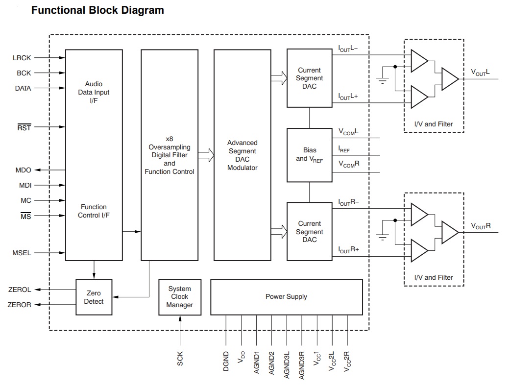
Block Diagram
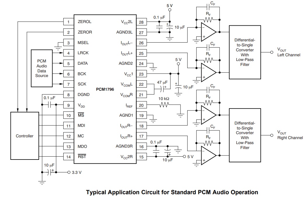
Application Diagram
Gerber View
Photos
PCM1795 Datasheet
Subscribe
Login
0 Comments


