Triac based lamp dimmer
- Rajkumar Sharma
- 58.728 Views
- easy
- Tested
- SKU: EL34732
- Quote Now
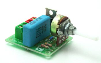
Triac based Indecent lamp dimmer is a simple circuit and it doesn’t requires additional power supply, works directly with 110V AC or 230V AC.
Description
It is a low cost dimmer circuit for adjusting the light brightness of incandescent, Halogen Lamp, Light Bulb load up to 250 W.
Features:
– Input supply: 230 VAC or 110 VAC
– Output: 250 W
– Triac controlled
– On board Potentiometer for adjusting level
– Power Battery Terminal (PBT) for easy input / output connection
– Four mounting holes of 3.2 mm each
– PCB dimensions 40 mm x 34 mm
Schematic
Circuit description
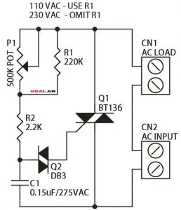
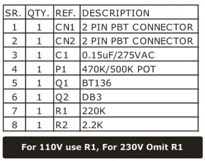
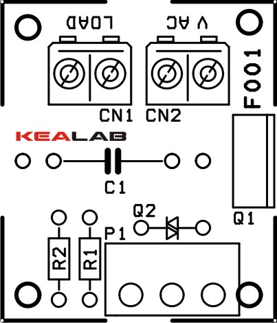
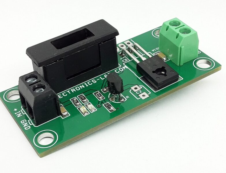
This kit consists of BT 136 Triac, resistors and capacitor. CN1 connector is for Load connections and CN2 connector for power supply connections.
BT136: It is a sensitive gate Triac, used in general purpose bidirectional switching and phase control applications where high sensitivity is required.
DB3: It is a DIAC that functions as a trigger diode with a fixed voltage reference. It can be used in conjunction with Triac for simplified gate control circuits or as a starting element in fluorescent lamp ballasts.
Working principle
This kit is used as a Light dimmer kit. It is used to adjust the brightness of the Halogen Lamp, Light Bulb up to 250 W. A power supply of 230 or 110 VAC is supplied to the kit at CN 2 connector and a light bulb is connected at the CN 1 connector. Using the POT we can adjust the brightness of the bulb.
Applications
It is used to adjust the brightness of incandescent, halogen lamp, light bulb up to 250 W.
Parts List





Great Article! =D
Rajkumar Sharma, forgot place your name! 😉
Tested the circuit, not working. Its a piece of…of not working electronics.
What you should test first is your electronics knowledge and skills. Next time try something simpler, maybe involving less than 5 electronic parts…
And now, seriously, take care about the P1 (470k pot.). Must have at least 0.25W power dissipation.
Potentiometer has parallel resistor for power dissipation. So its POT + Resistor
you can leave out R1 (220K) for 220v 120v supplies , and you can connect a 470k or 500k pot, you can use either one, it doesn’t really matter, R3 needs to be at least 3 watts and can be 2k2 to 4k7…ok? hope that helps you?
use the 470k or 500k pot, and DO NOT install the fixed 220k resistor, as it will have NO effect on the circuit, it will probably give more headaches than solving the problem, by the way…the 2k2 resistor should be at least 3 watts (or above) ,IF the 2k2 resistor doesn’t give you the desired effect? increase resistance to either 4k7 or 5k1, ok? hope that helps you?
Not working.
This kind of comments dont help us or other users to understand the condition of the circuit and be able to help you. You will need to be more specific.
This is working as it has been assembled and tested.
can i have pdf file for this one? thankyou!
We don’t have this on file and need to be created. Please allow us some time to prepare it.
Can i use 220V AC on this ?
Sure, it will work just fine.
Thank you for responding. I’ve another question: Is POT 470K or 500K which one is it and why?
If you can’t find a 500k pot you can try to use a 470k, it will work just fine.