Using Long Range 315MHz RF Wireless Transceivers with Arduino
- Emmanuel Odunlade
- https://twitter.com/emmaodunlade
- emmaodunlade@gmail.com
- 14.164 Views
- moderate
- Tested
Connectivity continues to be one of the most important features of any device in recent times, even for devices that are not directly connected to the internet, the need to send data from one device to the other is an important part of the ubiquitous world being built today. For designers, DIY hobbyist, and professionals alike, the choice of selecting the right communication module depends on the knowledge of the available options, as such, for today’s tutorial, we will look at the use of Long Range 315MHz RF Wireless Transceivers as a communication option for your Arduino projects.
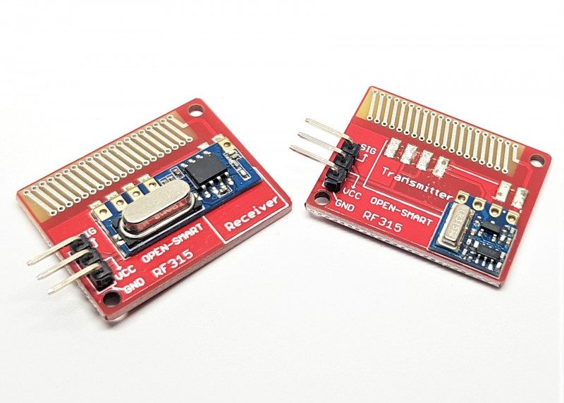
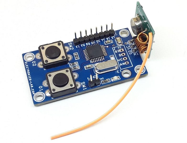
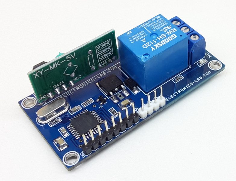
Short-range RF Transceivers like the 433MHz transmitters discussed in one of our previous post are very popular among DIY hobbyist and makers, however, their short-range was a bottleneck for users as they barely offer signal coverage for an area bigger than a standard room. To solve this and give makers more option and value, PMD Way developed these new 315/415 Mhz transceivers.
The new transceivers work the same way as the cheaper modules, maintaining the same pin configuration/layout, support the same libraries (like the VirtualWire library for Arduino) but the new modules, however, have a greater power output and a solid, convenient PCB antenna which increases range while also keeping things neat. The attainable transmitting power of the modules depends on the voltage applied at it’s VCC pin. For instance, when VCC is 5v, the modules are able to reach 150m range in open space, as such, the range can be improved further by increasing the supply voltage.
Some of the specifications of the long-range RF Modules are highlighted below:
- Transmitter working voltage: 4~12VDC
- Transmitter working current: 40mA
- Transmit power: 27dBm @ 12VDC
- Working frequency: 315MHz
- Transfer rate: 4.8kbps (max)
- Transmission distance: When supply power is 5V, the open area transmission distance is around 150 meters. To increase transmit range, you can increase the power to the transmitted up to 12V DC.
- Antenna: Onboard 315MHz dedicated PCB Antenna.
- Receiver operating voltage: 2~5.5V DC
- Receiver current: 2mA
- Sensitivity: -110db
For today’s tutorial, we will demonstrate how to use these modules by creating a simple sketch to send messages between two Arduino fitted with these modules. The first Arduino board will serve as the transmitter using a pushbutton such that when the push button is pressed, it sends an on/off data via the long-range RF modules to the second Arduino which serving as the receiver, which will turn the LED connected to it on/off in accordance with the signal received.
Required Components
The following components are required to build this project;
- 315MHz Long Range Wireless RF Module (1 Set of Transmitter and Receiver)
- Arduino Uno or compatible Boards (2)
- Breadboards (2)
- Pushbutton (1)
- Jumper Wires
- 330 Ohms
- LED (1)
- An external power supply for one Arduino. This can be an AC-DC wall wart, USB power bank, 9V battery, any power source to power the transmitter.
Two Arduino boards are required because we will build a complete system with a transmitter and receiver. If you don’t have an Arduino Uno available feel free to use any Arduino compatible board.
Schematics
As mentioned during the introduction, we will essentially build two projects. One will serve as the transmitter while the other will serve as the receiver as such, we have two schematics. The image of the short-range RF modules will be used since the connection is the same and the Long-range RF modules do not have a fritzing package.
Transmitter Schematics
The transmitter schematics is quite simple, we only need to connect a push-button and the transmitter of the 315MHz transceiver to the Arduino as shown in the image below.
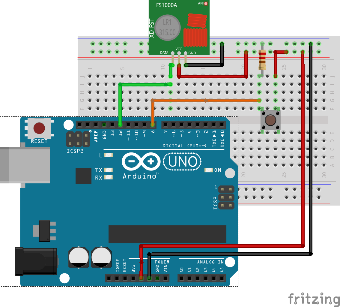
The pin-to-pin connection between the Arduino and the RF transmitter module is described below:
Arduino – RF Transmitter
5v - VCC
GND - GND
D12 - Data
Receiver Schematics
For the Receiver, we will connect a LED to the Arduino in addition to the Receiver of the 315MHz transceiver as shown in the image below.
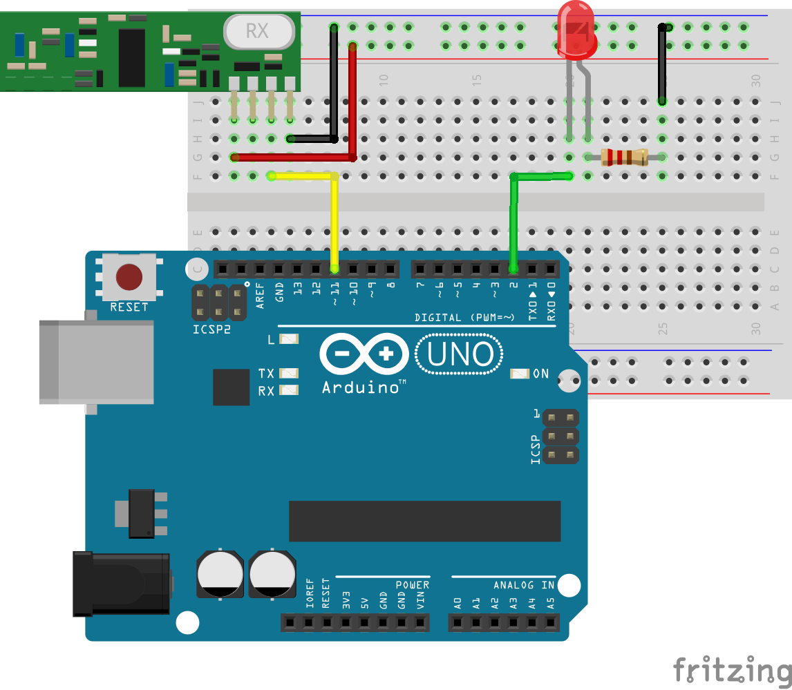
The pin-to-pin connection between the Arduino and the RF Receiver module is described below:
Arduino – RF Receiver
5v - VCC
GND - GND
D12 - Data
Go over the connections once more to ensure everything is as it should then proceed to the code section.
Code
The Code for this project is heavily dependent on the popular Virtual Wire Library. The library can be installed via the Arduino library manager or by downloading the library from the attached link and installing it by extracting it into the Arduino Libraries folder. The Virtualwire library comprises functions that allow us to perform actions like set the transmission power of the RF modules, encode the data, etc., generally reducing the amount of code we need to write to interact with the RF Modules.
With the library installed we can now proceed to write the code. Just like the schematics, we will write two sketches for this project; one for the transmitter and the other for the receiver.
Transmitter Sketch
We will start with the code for the transmitter. As mentioned during the introduction the sketch for the transmitter will simply send commands (a for ON, b for OFF) to the receiver when off.
We start as usual by importing the libraries that we will use, which in this case, is just the VirtualWire library.
// Transmitter
#include <VirtualWire.h>
Next, we create variables that will be used to hold different data like the characters to be sent by the transmitter, the buffer length, and the buffer name. We also declare the pin of the Arduino to which the push-button is connected.
uint8_t buf[VW_MAX_MESSAGE_LEN];
uint8_t buflen = VW_MAX_MESSAGE_LEN;
const char *on2 = "a";
const char *off2 = "b";
int button = 8;
With that done, we then proceed to the void setup() function. Here we invert the enable signal of the transmitter, use the vw_setup() function to specify the speed of communication in bps, use the vw_set_tx_pin() to specify the pins of the Arduino to which the transmitter pin is connected and finally, set the pin mode of the pin to which the push button is connected as input.
void setup()
{
  vw_set_ptt_inverted(true); // Required for RF Link modules
  vw_setup(300); // set data speed
  vw_set_tx_pin(12);
  pinMode(Button, INPUT);
}
With that done, we move into the void loop function, which is where the real action happens. The void loop function comprises of two if statements which check the state of the push-button. The vw_send() function is called to transmit the appropriate data based on the state of the push button.
void loop()
{
  if (digitalRead(button)==HIGH)
  {
    vw_send((uint8_t *)on2, strlen(on2)); // send the data out to the world
    vw_wait_tx(); // wait a moment
    delay(200);
  }
  if (digitalRead(button)==LOW)
  {
    vw_send((uint8_t *)off2, strlen(off2));
    vw_wait_tx();
    delay(200);
  }
}
The complete code for the transmitter is available below and also attached under the download section of the tutorial.
// transmitter sketch

#include <VirtualWire.h>
uint8_t buf[VW_MAX_MESSAGE_LEN];
uint8_t buflen = VW_MAX_MESSAGE_LEN;
const char *on2 = "a";
const char *off2 = "b";
int button = 8;

void setup()
{
  vw_set_ptt_inverted(true); // Required for RF Link modules
  vw_setup(300); // set data speed
  vw_set_tx_pin(12);
  pinMode(Button, INPUT);
}

void loop()
{
  if (digitalRead(button)==HIGH)
  {
    vw_send((uint8_t *)on2, strlen(on2)); // send the data out to the world
    vw_wait_tx(); // wait a moment
    delay(200);
  }
  if (digitalRead(button)==LOW)
  {
    vw_send((uint8_t *)off2, strlen(off2));
    vw_wait_tx();
    delay(200);
  }
}
Next is the Receiver Sketch.
Receiver Sketch
The sketch for the receiver is quite straightforward. When data is received from the transmitter, the receiver processes the data and issue commands turns the LED ON or OFF depending on the command that was received.
We start the sketch as usual, by including the library that will be used, which is still the same virtual wire library used for the transmitter sketch. Next, we create variables buf and buflen that will be used to store the data received from the transmitter along with its length and also declare the pin of the Arduino to which the LED is connected.
#include <VirtualWire.h>
uint8_t buf[VW_MAX_MESSAGE_LEN];
uint8_t buflen = VW_MAX_MESSAGE_LEN;
int ledpin = 2;
With that done, we write the void setup() function.
We start the function by inverting the state of the enable pin, set the communication speed to 300bps to match that of the transmitter, set the rx pin as D11, start the receiver -> set it to listen for incoming traffic, and then specify the mode of the pin to which the LED is connected.
void setup()
{
  vw_set_ptt_inverted(true); // Required for RF link modules
  vw_setup(300);
  vw_set_rx_pin(11);
  vw_rx_start();
  pinMode(ledpin, OUTPUT);
}
up next is the void loop() function.
The void loop() function is quite straight forward. We check if data was received into the buffer by calling the vw_get_message function. If data was received, a select case statement is then used to compare the data that was received. If “a” was received, the LED is turned ON and if “b” was received, the LED is turned OFF.
void loop()
{
  if (vw_get_message(buf, &buflen))
  {
    switch(buf[0])
    {
    case 'a':
      digitalWrite(ledpin, HIGH);
      break;
    case 'b':
      digitalWrite(ledpin, LOW);
      break;
    }
  }
}
That’s it! The complete code for the receiver is below and also attached under the download section of the project.
// receiver sketch

#include <VirtualWire.h>
uint8_t buf[VW_MAX_MESSAGE_LEN];
uint8_t buflen = VW_MAX_MESSAGE_LEN;
int ledpin = 2;

void setup()
{
  vw_set_ptt_inverted(true); // Required for RF link modules
  vw_setup(300);
  vw_set_rx_pin(11);
  vw_rx_start();
  pinMode(ledpin, OUTPUT);
}

void loop()
{
  if (vw_get_message(buf, &buflen))
  {
    switch(buf[0])
    {
    case 'a':
      digitalWrite(ledpin, HIGH);
      break;
    case 'b':
      digitalWrite(ledpin, LOW);
      break;
    }
  }
}
Demo
Go over the connections once again to ensure all is correct then connect both devices to the computer and upload the sketch one after the other.
With the sketches uploaded, power both devices and press the push-button on the transmitter. You should see the LED connected to the receiver light up.
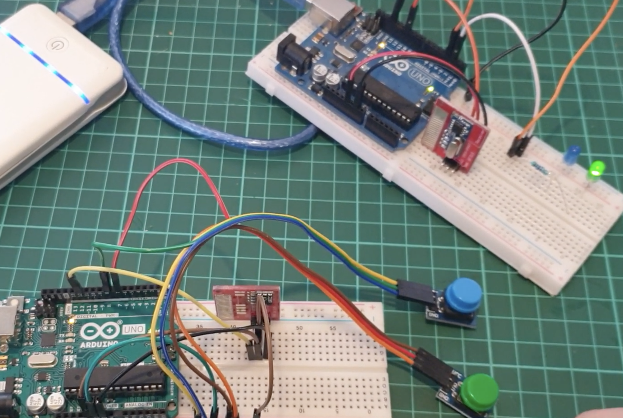
The long-range RF modules provide an alternative way to implement cheap communication over somewhat large distances as such, it is worth considering for your low-budget, local network of devices project.
That’s it for today’s project. Feel free to ask any questions you might have about this via the comment section.
A video of the project in action can be found on youtube.


Well, that is all very interesting, its quite simple with the proper boards. Thanks for the idea. In Facebook I can not download the Archive.zip
Hi bro , Thanks for uploading this article. I have doubt, please clarify that. Actually working perfectly i was used spst switch in transmitter line. whenever i switched on spst switch receiver side LED was light upped. On that time i have switched off main power of transmitter, but receiver side LED lighted upped continually. I need light down on receiver side when transmitter main power off (while spst switch on condition)
Well you’ve ripped off the article directly from https://pmdway.com/blogs/product-guides-for-arduino/tutorial-using-long-range-315mhz-rf-wireless-transceivers-with-arduino
This is our own write-up based on this tutorial. In any case, I added a reference to the source article above. Thanks