Variable Range LED Voltmeter
- Rajkumar Sharma
- 19.418 Views
- moderate
- Tested
- SKU: EL37428
- Quote Now
This project is a Variable Range LED voltmeter.
Description
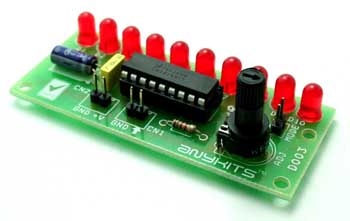
This is a variable range LED bar graph voltmeter project. It is a simple and less expensive project that displays voltage of a given source with the help of 10 LEDs. The project is based on the famous LM3914 IC from Texas instruments.
Working
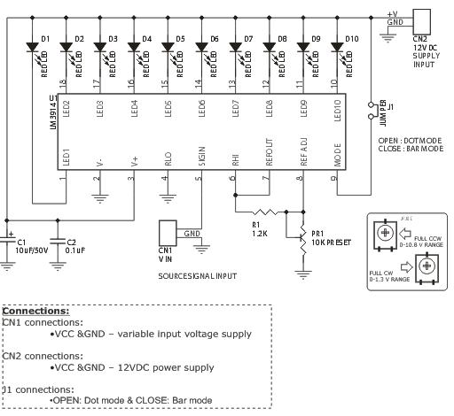
The project is used as a Variable Range LED Voltmeter. The LEDs indicate the range of the input voltage applied. A power supply of 12 VDC is applied through the CN2 connector, and the variable input voltage supply is applied to the CN1 connector. IC LM3914 is a dot/bar display driver; it senses the analog voltage levels and displays its range on the LEDs.
The LEDs indicate depending upon the variable input voltage applied. Using the jumper we can select the mode of LED display. When the jumper is open it is in dot mode and when it is closed it is in bar mode. Range adjustable 0-1.3 V and 0-10.8V.
Specifications
Input : 12 VDC @ 190 mA
Range : 0 – 1.3 V and 0 – 10.8 V adjustable with onboard preset
Output : 10 LED’s
Two Modes, Bar and Dot selectable by a jumper
Very low current consumption, typical 200 mA
Header pins for connecting power and voltage in
Four mounting holes of 3.2 mm each
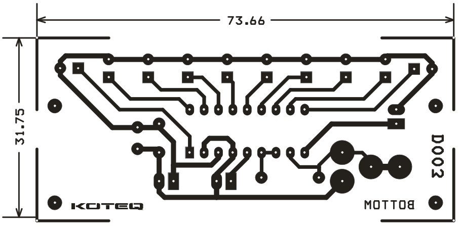
PCB dimensions 32 mm x 74 mm
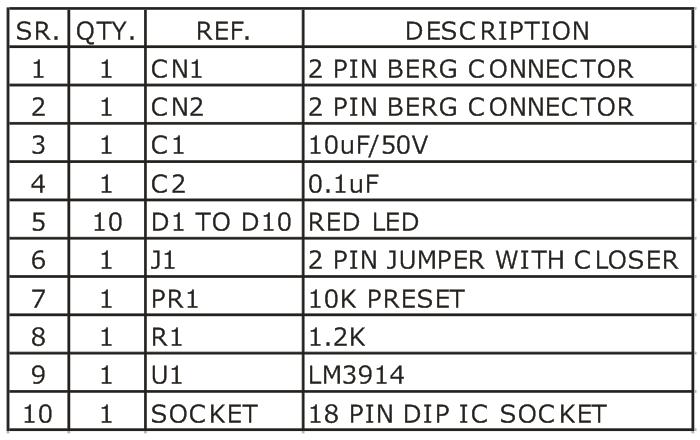
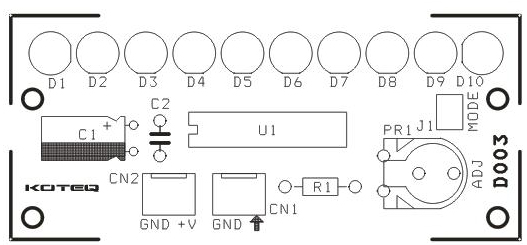
Schematic




So beautiful design and explanations
Thank you
Best to read the TI Application Note and take special NOTE OF THE GROUNDING (at a common point) > http://www.ti.com/lit/ds/snvs761b/snvs761b.pdf <