Video Streaming Server on ESP32-CAM
- Emmanuel Odunlade
- https://twitter.com/emmaodunlade
- emmaodunlade@gmail.com
- 28.731 Views
- moderate
- Tested
A while back, I noticed an ESP32 based Camera board called the ESP32-CAM on LCSC.com, and planned on getting one to play with but didn’t get the chance until recently when I saw a tutorial by Rui Santos based on the board. I feel its a nice board and today’s tutorial will focus on building a Video Streaming Server using the ESP32-CAM board.
The ESP32-CAM is very cheap (costs less than $10), a small camera module, based on the ESP32-S chip from AI-thinker. It essentially comprises an OV2640 camera embedded with an ESP32 module with several GPIOs to which peripherals (sensors and actuators) can be connected, and a microSD card slot which could be useful in storing images from the camera. Highlighting the fact that it was designed for stand-alone camera-based applications only, the ESP32-CAM doesn’t come with features like a USB port, etc, all of which are available on regular ESP-32 boards. The lack of USB ports also means the lack of an FTDI chip as such, to program the board, you will need to use an FTDI Programmer.
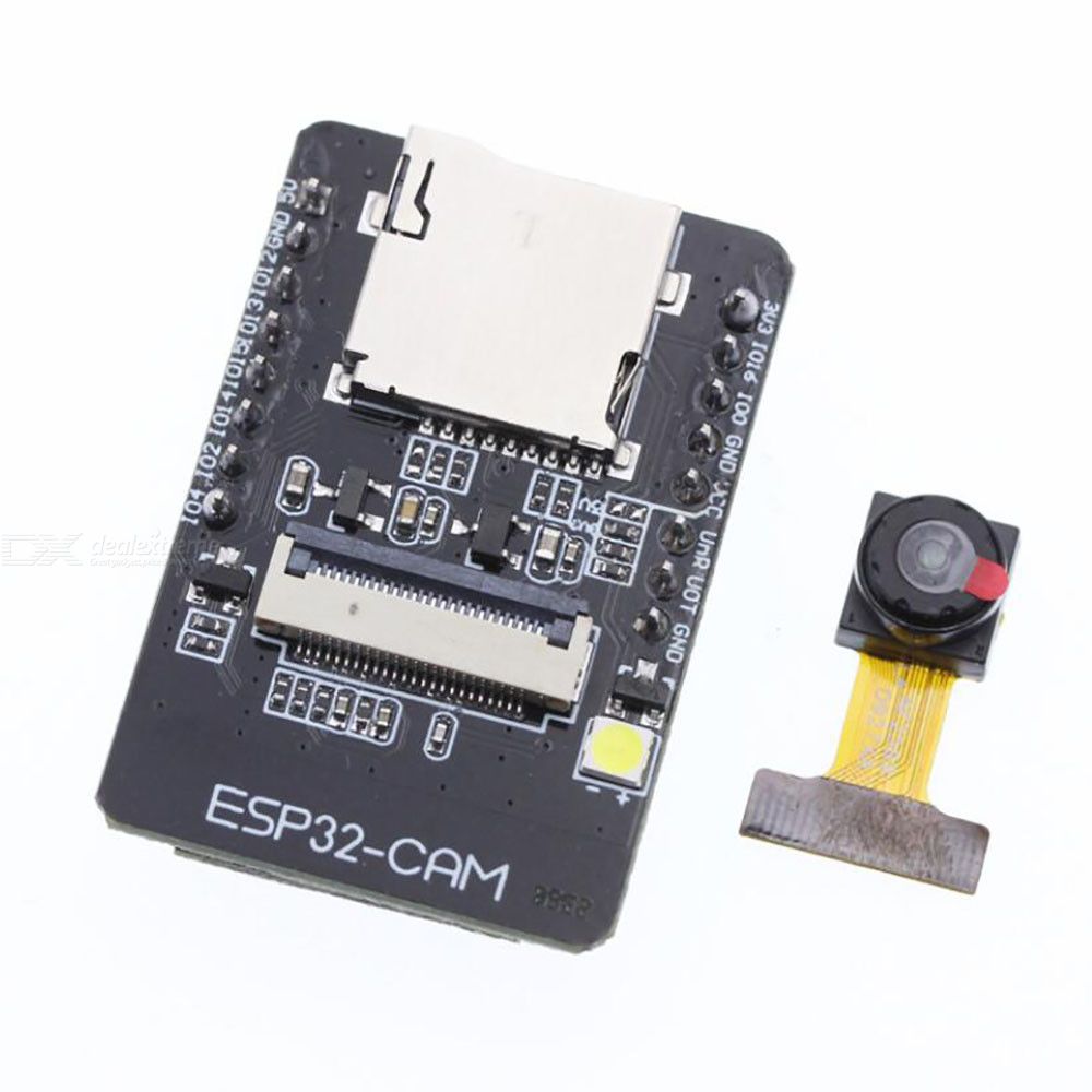
Some of the features of the ESP32-CAM board are highlighted below:
- 802.11b/g/n Wi-Fi BT SoC module with support for STA/AP/STA+AP operation mode
- Low power 32-bit CPU, can also serve the application processor
- Up to 160MHz clock speed, summary computing power up to 600 DMIPS
- Built-in 520 KB SRAM, external 4MPSRAM
- Supports UART/SPI/I2C/PWM/ADC/DAC
- Support OV2640 and OV7670 cameras, and has a built-in flash lamp
- Support image WiFI upload
- SD card Slot
- Embedded Lwip and FreeRTOS
- Support Smart Config/AirKiss technology
- Support for serial port local and remote firmware upgrades (FOTA)
To demonstrate how the ESP32-CAM works, we are going to build a Video Streaming Server whose IP address can be accessed from outside to get a live stream from the ESP32-CAM Camera.
The steps are quite easy and at the end of the tutorial, you should be familiar with the ESP32-CAM, enough to build a more astounding project with it.
Required Components
The components required for this project include;
- The ESP32-CAM
- 3.3V FTDI Programmer
- Jumper Wires
- Bread Board
The components can be bought from the attached links. For the FTDI, the SparkFun’s FTDI Basic Breakout was used but you can decide to use any other similar board with 3.3V logic level.
Schematics
The ESP32-CAM comes with the camera connected, and if this is different in your case, all you need do is connect the camera to the port provided. This leaves us with the connection between the ESP32-CAM and the FTDI Programmer. The FTDI programmer communicates with the ESP32-CAM over UART as such, it will be connected to the UART pin of the ESP32-CAM. The connection is illustrated in the schematics below;
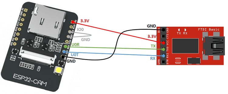
Go over the connection once more to ensure everything is as it should be.
CODE
We will use the Arduino IDE for this project, as such, there is a need for us to set up the Arduino IDE with the board files for the ESP32. Follow the steps detailed in this tutorial we wrote a while back on “Programming the ESP32 with the Arduino IDE” to get it done.
The code for today’s project is based on the CameraWebserver example in the ESP32 Library. The idea behind the project is simple, the ESP32-CAM board is configured as a web server, serving live feed from the camera on a webpage, so any browser on the same network as the ESP can view the live feed by going to the board’s IP address.
The code uses the esp_camera library along with the WiFi.h library. The esp_Camera library contains functions that grant access to the camera and functions to take pictures and record videos among other things, while the ESP’s WiFi.h library comprises functions that allow us to set up the ESP32 as a web server among other things. These libraries are installed when you install the ESP32 Arduino IDE add-on, as such, they require no special installation process.
As usual, I will do a quick explanation of some parts of the code and provide the complete code at the end of the project.
The code starts with the inclusion of all the libraries that we will use. Depending on your version of the ESP32 library/add-on, the Camera_pins.h file will either be attached as a file to the sketch or it’s content copied into the sketch. In our case, it was attached as a file, and the file has been added to the files under the download section.
#include "esp_camera.h"
#include <WiFi.h>
#include "camera_pins.h"
Next, the model of the camera being used is being specified. In this case, we will be using the AI-Thinker camera, so it is specified.
// Select camera model
//#define CAMERA_MODEL_WROVER_KIT
//#define CAMERA_MODEL_ESP_EYE
//#define CAMERA_MODEL_M5STACK_PSRAM
//#define CAMERA_MODEL_M5STACK_WIDE
#define CAMERA_MODEL_AI_THINKER
Next, we provide the credentials of the access point to which the ESP32 is to be connected and initialize the StartCameraServer function.
const char* ssid = "ssid";
const char* password = "password";

void startCameraServer();
Next is the void setup() function. We start the function by initializing serial communication, after which we configure the camera, setting its pins to that of the variables stored in the Camera_pins.h file. We also set things like its frequency and pixel format among others.
camera_config_t config;
  config.ledc_channel = LEDC_CHANNEL_0;
  config.ledc_timer = LEDC_TIMER_0;
  config.pin_d0 = Y2_GPIO_NUM;
  config.pin_d1 = Y3_GPIO_NUM;
  config.pin_d2 = Y4_GPIO_NUM;
  config.pin_d3 = Y5_GPIO_NUM;
  config.pin_d4 = Y6_GPIO_NUM;
  config.pin_d5 = Y7_GPIO_NUM;
  config.pin_d6 = Y8_GPIO_NUM;
  config.pin_d7 = Y9_GPIO_NUM;
  config.pin_xclk = XCLK_GPIO_NUM;
  config.pin_pclk = PCLK_GPIO_NUM;
  config.pin_vsync = VSYNC_GPIO_NUM;
  config.pin_href = HREF_GPIO_NUM;
  config.pin_sscb_sda = SIOD_GPIO_NUM;
  config.pin_sscb_scl = SIOC_GPIO_NUM;
  config.pin_pwdn = PWDN_GPIO_NUM;
  config.pin_reset = RESET_GPIO_NUM;
  config.xclk_freq_hz = 20000000;
  config.pixel_format = PIXFORMAT_JPEG;
Next, we check if the board has a PSRAM and initialize it setting the frame size and JPEG quality.
if(psramFound()){
   config.frame_size = FRAMESIZE_UXGA;
   config.jpeg_quality = 10;
   config.fb_count = 2;
 } else {
   config.frame_size = FRAMESIZE_SVGA;
   config.jpeg_quality = 12;
   config.fb_count = 1;
 }
Next, we initialize the camera using the configurations created
// camera init
esp_err_t err = esp_camera_init(&config);
if (err != ESP_OK) {
  Serial.printf("Camera init failed with error 0x%x", err);
  return;
}
and set the properties of the camera sensor being used.
  sensor_t * s = esp_camera_sensor_get();
  //initial sensors are flipped vertically and colors are a bit saturated
  if (s->id.PID == OV3660_PID) {
    s->set_vflip(s, 1);//flip it back
    s->set_brightness(s, 1);//up the blightness just a bit
    s->set_saturation(s, -2);//lower the saturation
  }
  //drop down frame size for higher initial frame rate
  s->set_framesize(s, FRAMESIZE_QVGA);

#if defined(CAMERA_MODEL_M5STACK_WIDE)
  s->set_vflip(s, 1);
  s->set_hmirror(s, 1);
#endif
Next, we connect the node to the access point using the credentials provided earlier and verify the connection status.
WiFi.begin(ssid, password);

 while (WiFi.status() != WL_CONNECTED) {
   delay(500);
   Serial.print(".");
 }
 Serial.println("");
 Serial.println("WiFi connected");
With the WiFi connected, we call the StartCameraServer() function which automatically begins streaming the camera feed to a webpage that can be accessed via the IP address of the board (displayed on the serial monitor using the Wifi.localIP()) function).
 startCameraServer();

  Serial.print("Camera Ready! Use 'http://");
  Serial.print(WiFi.localIP());
  Serial.println("' to connect");
}
The void loop() function just introduces a delay at every refresh point.
The StartCameraServer() function is one of the functions built into the ESP32 library. You can check it out to better understand how it works.
The complete code for the project is provided below and also attached under the download section.
#include "esp_camera.h"
#include <WiFi.h>
#include "camera_pins.h"

//
// WARNING!!! Make sure that you have either selected ESP32 Wrover Module,
//            or another board which has PSRAM enabled
//

// Select camera model
//#define CAMERA_MODEL_WROVER_KIT
//#define CAMERA_MODEL_ESP_EYE
//#define CAMERA_MODEL_M5STACK_PSRAM
//#define CAMERA_MODEL_M5STACK_WIDE
#define CAMERA_MODEL_AI_THINKER


const char* ssid = "ssid";
const char* password = "password";

void startCameraServer();

void setup() {
  Serial.begin(115200);
  Serial.setDebugOutput(true);
  Serial.println();

  camera_config_t config;
  config.ledc_channel = LEDC_CHANNEL_0;
  config.ledc_timer = LEDC_TIMER_0;
  config.pin_d0 = Y2_GPIO_NUM;
  config.pin_d1 = Y3_GPIO_NUM;
  config.pin_d2 = Y4_GPIO_NUM;
  config.pin_d3 = Y5_GPIO_NUM;
  config.pin_d4 = Y6_GPIO_NUM;
  config.pin_d5 = Y7_GPIO_NUM;
  config.pin_d6 = Y8_GPIO_NUM;
  config.pin_d7 = Y9_GPIO_NUM;
  config.pin_xclk = XCLK_GPIO_NUM;
  config.pin_pclk = PCLK_GPIO_NUM;
  config.pin_vsync = VSYNC_GPIO_NUM;
  config.pin_href = HREF_GPIO_NUM;
  config.pin_sscb_sda = SIOD_GPIO_NUM;
  config.pin_sscb_scl = SIOC_GPIO_NUM;
  config.pin_pwdn = PWDN_GPIO_NUM;
  config.pin_reset = RESET_GPIO_NUM;
  config.xclk_freq_hz = 20000000;
  config.pixel_format = PIXFORMAT_JPEG;
  //init with high specs to pre-allocate larger buffers
  if(psramFound()){
    config.frame_size = FRAMESIZE_UXGA;
    config.jpeg_quality = 10;
    config.fb_count = 2;
  } else {
    config.frame_size = FRAMESIZE_SVGA;
    config.jpeg_quality = 12;
    config.fb_count = 1;
  }

#if defined(CAMERA_MODEL_ESP_EYE)
  pinMode(13, INPUT_PULLUP);
  pinMode(14, INPUT_PULLUP);
#endif

  // camera init
  esp_err_t err = esp_camera_init(&config);
  if (err != ESP_OK) {
    Serial.printf("Camera init failed with error 0x%x", err);
    return;
  }

  sensor_t * s = esp_camera_sensor_get();
  //initial sensors are flipped vertically and colors are a bit saturated
  if (s->id.PID == OV3660_PID) {
    s->set_vflip(s, 1);//flip it back
    s->set_brightness(s, 1);//up the blightness just a bit
    s->set_saturation(s, -2);//lower the saturation
  }
  //drop down frame size for higher initial frame rate
  s->set_framesize(s, FRAMESIZE_QVGA);

#if defined(CAMERA_MODEL_M5STACK_WIDE)
  s->set_vflip(s, 1);
  s->set_hmirror(s, 1);
#endif

  WiFi.begin(ssid, password);

  while (WiFi.status() != WL_CONNECTED) {
    delay(500);
    Serial.print(".");
  }
  Serial.println("");
  Serial.println("WiFi connected");

  startCameraServer();

  Serial.print("Camera Ready! Use 'http://");
  Serial.print(WiFi.localIP());
  Serial.println("' to connect");
}

void loop() {
  // put your main code here, to run repeatedly:
  delay(10000);
}
Demo
With the ESP-32 CAM connected to the FTDI programmer, ensure the GPIO O pin is connected to GND, then connect the programmer to your PC and follow this next steps to upload the code:
- Go to Tools > Board and select ESP32 Wrover Module
- Go to Tools > Port and select the COM port the ESP32/FTDI is connected to
- In Tools > Partition Scheme, select “Huge APP (3MB No OTA)“
- Press the ESP32-CAM on-board RESET button
- Then, click the upload button to upload the code
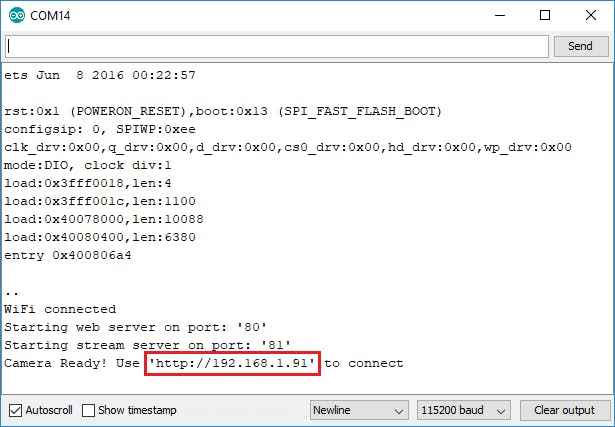
After uploading the code, disconnect GPIO 0 from GND and Open the Serial Monitor with the baud rate of 115200 (same as the serial.begin() function). Press the ESP32-CAM on-board Reset button, you should see the IP address of the ESP printed in the Serial Monitor as shown below.
To access the feeds from the camera, open a browser on a device on the same network as the ESP, and enter the ESP32-CAM IP address into the address bar. Press the Start Streaming button on the resulting page and you should see the video being streamed.
Quite a number of advancements can be made to the project. With little or no additional coding, you can easily connect the project to your home assistant, so you can view the stream from the Home Assistant app and with a little more effort and an SD Card, we can take this do things like facial recognition.
That’s it! Feel free to reach me via the comment section with questions about the project and also let me know if you will be making any improvements to it.


How can I upload the video stream to cloud storage directly from esp32 cam board?
I too want to know about that. Please help me out.
Can u find out how we directly stream video from esp32cam to cloud storage?
i wanna report for this project ,can you send please
Sorry, I don’t understand, What do you need?
I need to connect to the house from another wifi or from the data I have in 4G mobile. It can only be connected via wifi, to which ESP32-CM is connected …