Romeo BLE – An Arduino Based Powerful Robot Control Board With Bluetooth 4.0
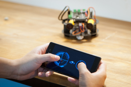
Romeo BLE is an all-in-one Arduino based control board specially designed for robotics applications from DFRobot. This platform is open source and it’s powered by thousands of publicly available open-sourced codes. Romeo BLE can easily be expanded using Arduino shields. The most important feature—Bluetooth 4.0 wireless communication, allows the board to receive commands via Bluetooth. So, users can now use their smartphone, tablet, or computer to interact with the control board.
Even the codes can be uploaded over Bluetooth a USB Bluno Link adapter, without requiring any wired USB connection between the board and a PC. This is a great advantage for mobile applications where codes are debugged and uploaded frequently.
The Romeo BLE also includes two integrated two-channel DC motor drivers and wireless sockets, which makes project development more hassle-free. One can start the project immediately without needing an additional motor driver circuitry. The motor driving section also supports extra servos which need more current.
There are two ways to power the Romeo BLE board. But, the polarity must be correct. Otherwise, the board may get permanently damaged as there exists no reverse polarity protection. The two powering methods are:
- Power from USB: Plug in the USB cable to the Romeo controller from a power source (i.e. wall jack or computer). If the input voltage and current are sufficient, the Romeo BLE board should turn on and a LED should light up. While powered from USB, do NOT connect anything else like motor, servo etc. except LED. Because the USB can only provide 500mA current which is certainly not enough for driving loads like motors.
- Power from External Power Supply: Connect the ground wire from your supply to the screw terminal labeled “GND” on Romeo board, and then connect the positive wire from your supply to the screw terminal labeled “VIN”. The maximum acceptable input voltage is 23 volts. Do not exceed this value anyway.
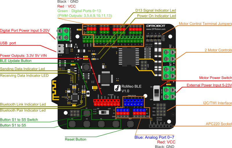
Specifications:
- Microcontroller: ATmega328P
- Bootloader: Arduino UNO
- Onboard BLE chip: TI CC2540
- 14 Digital I/O ports
- 6 PWM Outputs (Pin11, Pin10, Pin9, Pin6, Pin5, Pin3)
- 8 10-bit analog input ports
- 3 I2Cs
- 5 Buttons
- Power Supply Port: USB or DC2.1
- External Power Supply Range: 5-23V
- DC output: 5V/3.3V
- Size: 94mm x 80mm
Features:
- Auto sensing/switching external power input
- Transmission range: 70m in free space
- Support Bluetooth remote update the Arduino program
- Support Bluetooth HID
- Support iBeacons
- Support AT command to config the BLE
- Support Transparent communication through Serial
- Support the master-slave machine switch
- Support USB update BLE chip program
- Support Male and Female Pin Header
- Two-way H-bridge motor Driver with 2A maximum current
- Integrated sockets for APC220 RF Module
You can program Romeo BLE using Arduino IDE version 1.8.1 or above. Select Arduino UNO from Tools –> Boards in the IDE. Go to arduino.en.cc to download the latest version of Arduino IDE. Read the Romeo BLE wiki to learn more.


