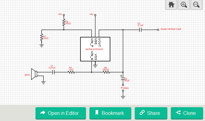
This design of acoustic sound receiver features low power operational amplifier. It has rail-to-rail input/output and 0.85mA supply current per amplifier. It uses piezo speaker as its microphone that can be attached to easily due to its size and dimension.
The circuit is comprised of MCP6L91RT-E/OT 10 MHz, 850 µA operational amplifier that is used to amplify the sound signal. The low-pass filter is used to allow low frequency signal to pass while attenuating high frequency signal or above cut-off frequency of the system to prevent distortions and unnecessary signal. The piezo speaker is used as a microphone or a sound receiver in this circuit. Its size and dimensions is well suited for this application.
The circuit is suitable for different types of acoustic guitar. Since it can be attached easily, the old and other traditional instruments can be developed and modified so that it can continue its service even for the digital era. It can be interfaced to different applications which is not limited to musical instrument.
Simple Acoustic Guitar Sound Receiver – [Link]





It is a horrible circuit:
1)The high impedance signal from the piezo transducer is loaded down by the very low 1k input resistance of the inverting amplifier. The amplifier should be non-inverting with a high input resistance then its gain does not need to be so high. Most circuits in Google are non-inverting with a 3M ohms input resistance.
2) There is no “lowpass” filter. The high frequency resonances of the piezo are not attenuated.
3) The maximum allowed supply for the opamp is only 7V so the 9V shown will probably destroy it.