Author: Pablo E. Leibovich and Alberto I. Leibovich
Introduction
Climate change and its consequences have increased concern about how to replace fossil fuels with cleaner and more sustainable alternatives for electricity generation. Renewable energy sources, such as solar, wind, hydropower, biomass, and geothermal energy, have emerged as real solutions with huge development. They refer not only to large wind or solar farms but also to domestic generation, with small solar panels or wind turbines that replace or reduce the cost of energy from the public electric grids.
However, these sources typically generate DC electricity, while most applications and the electrical grid operate on AC. Inverters bridge this gap by converting DC power into AC power, making renewable energy sources compatible with existing infrastructure.
Similar considerations can be related to automotive applications. Various devices and portable equipment require AC power which may be not available on a trail, campsite, or different locations where the only available electrical power can be received from the car battery. As it is a DC power supply, inverters are mandatory to get the required AC power from the battery.
To implement the power conversion, DC-AC inverters usually apply the Pulse Width Modulation technique. PWM is a widely used technique where switches like Power MOSFETs are controlled with pulses of variable widths, to obtain an automatic control and regulation of AC voltage output (and its frequency), keeping it at the nominal value independent of the output load.
There are several studies and technologies that have been developed to determine how to obtain a better response from the inverter control system. From all these resources, and evaluating the available devices in the market, it can be concluded that inverters that change the output voltage according to the changes in the load and generate a sinusoidal AC voltage waveform are the best alternative to obtain AC power from DC sources without generating electromagnetic compatibility issues, such as switching losses or harmonic generation.
This article describes how to build a sine wave-based inverter useful for automotive and renewable energy applications. The article explains the implemented logic, the SLG47004 AnalogPAK’s configuration and the obtained results of a highly integrated inverter. The internal design was implemented in the Go Configure Software Hub. The complete design file can be found here: Sine Wave-Based Inverter.gp.
Design Description
To obtain DC-AC conversion, PWM-based inverters regulate the output voltage by changing the width of the pulses generated at a comparatively high frequency. Therefore, the output voltage depends on the switching frequency and pulse width, which varies according to the value of the load connected to the output. Several methods of generating pulse width modulation have been studied, being sinusoidal pulse width modulation (SPWM) the widely used in power electronics as the modulation method for PWM inverters.
As mentioned before, a single-phase design requires switching transistors, MOSFETS or IGBTs on each arm of an H-bridge with antiparallel freewheeling diodes to discharge current when the switch is turned off, as it is shown in Figure 1.

Q1-Q4 signals are the SPWM outputs of the inverter controller.
An inverter controller can be implemented by considering the block diagram shown in Figure 2.

A high-frequency triangular waveform, generally in several kHz, is necessary to generate the SPWM signals. This task is implemented with finite state machines (FSM)/Counters, D-type Flip Flops, and a low pass external filter. It is referenced as HF Triangle Generator in the previous diagram and is based on the AN-CM-265 Programmable Limits PWM application note. The generator output is a PWM signal with triangular variation of duty cycle, which is then filtered by a low pass filter to obtain a triangular shape.
This triangular waveform is compared to a low voltage 50 or 60 Hz sine waveform with the Analog Comparators of the AnalogPAK. With this comparison, the sinusoidal modulation of the PWM is implemented. The modulation scheme, and the obtained signal, are shown in Figure 3.
Finally, an inverter gate is used to generate the complementary signals for the SPWM outputs (S1 to S4 in Figure 1). The output of the H-Bridge contains an LC-filter so the high-frequency component of the SPWM is filtered and, finally, the sinusoidal waveform of 50 or 60 Hz is applied to the load.

To obtain better results, the frequency ratio between the triangular and the sinusoidal waveforms must be an integer N = fC/fS, where fC is the carrier frequency (the triangular waveform) and fS is the modulation frequency (the sine waveform). With this condition, the number of voltage pulses per half-cycle results in N/2.
The amplitude of the output signal can be controlled by changing the amplitude low-frequency sine waveform. If a short mathematical analysis is performed, a modulation index m can be defined as the ratio between the amplitude of the low frequency sine wave (VS) and the high frequency triangular wave (VC):
For regulation range, m must be equal or less than 1.0. If the previous condition is considered, the output voltage of the H-bridge controlled by SPWM results:
Where VDC is the input DC voltage to the inverter.
In this article, the fixed frequency sine waveform is generated with a Wien oscillator based on the AnalogPAK’s internal OPAMP and a RC external network to set the oscillation frequency. In Figure 4, the schematic circuit can be seen.

As one of the main issues of the Wien oscillator is its frequency instability, the OPAMP’s gain must be exactly 2 to start oscillating without distorting the sine wave output signal. To do so, precision resistors should be used. Also, as not only the temperature changes but also the voltage fluctuations, and the OPAMP’s imperfections can affect the output, a soft clipping circuit is included.
The offset of the sine wave is set by the VREF voltage (corresponding to VDD/2), and the amplitude is controlled by an automatic gain control (AGC) implemented with another internal OPAMP and the digital rheostats of the AnalogPAK. The amplitude control is implemented as output feedback, to regulate the output voltage of the inverter. This control is implemented with internal Analog Comparators that vary the rheostat counter depending on the output voltage. The corresponding schematic circuit is shown in Figure 5.

Sine Wave-Based Inverter Implementation
As described earlier, the High Frequency Triangular Waveform generator, is based on the AN-CM-265 Programmable Limits PWM application note, so a high frequency PWM signal with a triangular variation of duty cycle is obtained. The implementation of the generator can be seen in Figure 6.
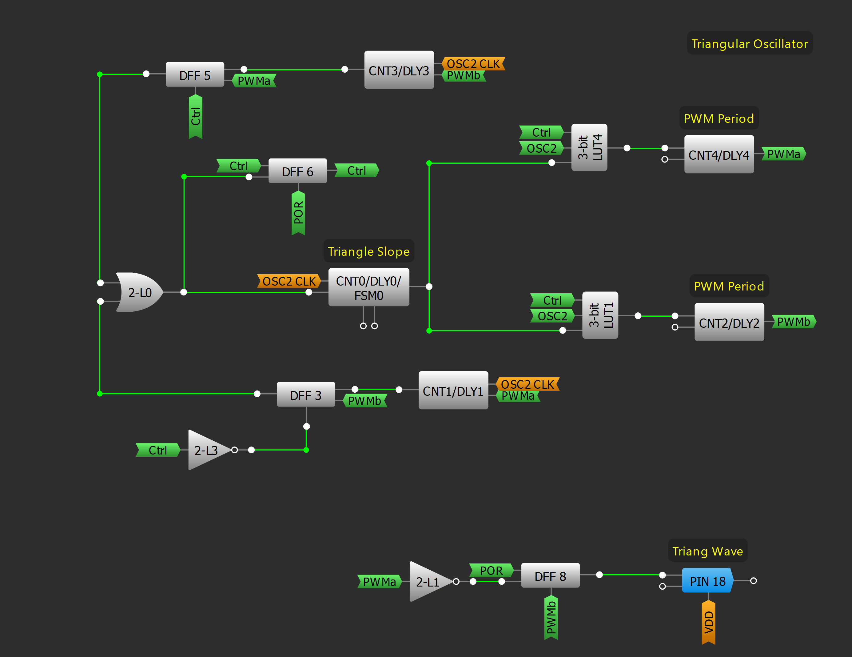
The generator is based on the internal OSC2 25 MHz oscillator, configured for an output frequency of 12.5 MHz. This clock is the time base used for PWM generation with CNT2 and CNT4, which generate the corresponding square waveform with the desired duty cycle. Counter data of both counters is defined to obtain a PWM of 50 KHz. The configuration of both counters can be seen in Figures 7 and 8.
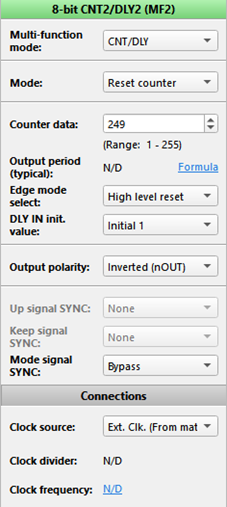
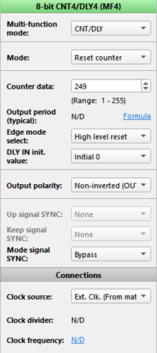
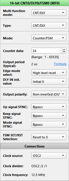
To vary the generated duty cycle, CNT0/DLY0/FSM0 is used to change the relative phase of the previously mentioned counters. The slope of triangular duty cycle variation is configured by setting CNT0 counter data.
With the configuration shown in Figure 9, the triangular waveform has a period of 1 ms (it must be considered the positive ramp and the negative one), so a 1 kHz triangular waveform is obtained.
It is important to mention that in this article, a 50 Hz SPWM inverter is implemented. If desired, it can be modified for 60 Hz or other frequencies by only changing the period of the triangular and sine waveform.
The high frequency PWM with triangular variation is connected to PIN 18, where the previously mentioned low pass filter is connected. This filter is based on a first-order RC design, with a 1.5 kΩ resistor and a 10 nF capacitor. With these values, the cut-off frequency of the filter results 10.6 KHz.
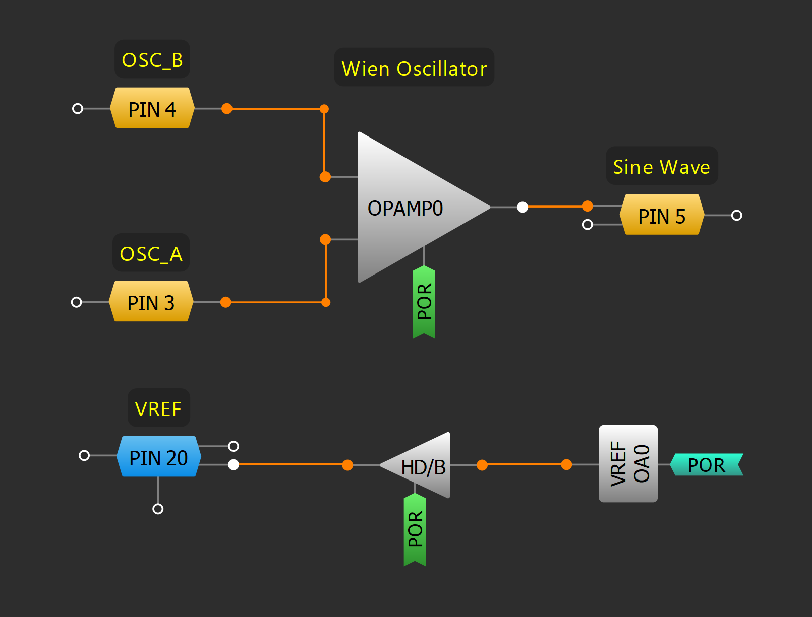
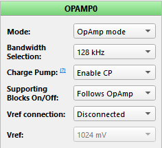
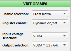
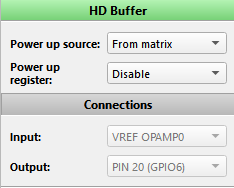
As described earlier, another oscillator must be implemented. In this case, a sinusoidal oscillator is required to generate the SPWM. Therefore, a Wien-based oscillator is implemented using the OPAMP0 of the AnalogPAK. The reference voltage necessary to generate the sine wave with VDD/2 offset is obtained from the VREF of this operational amplifier and with the HD Buffer. Its block diagram is shown in Figure 10 and the configuration of the mentioned blocks is shown in Figures 11, 12 and 13 respectively.
In Section 3, the SPWM principles were described. It was mentioned that the amplitude of the sinusoidal waveform allows the inverter to regulate the voltage output. To do so, the regulator shown in Figure 5 is implemented.
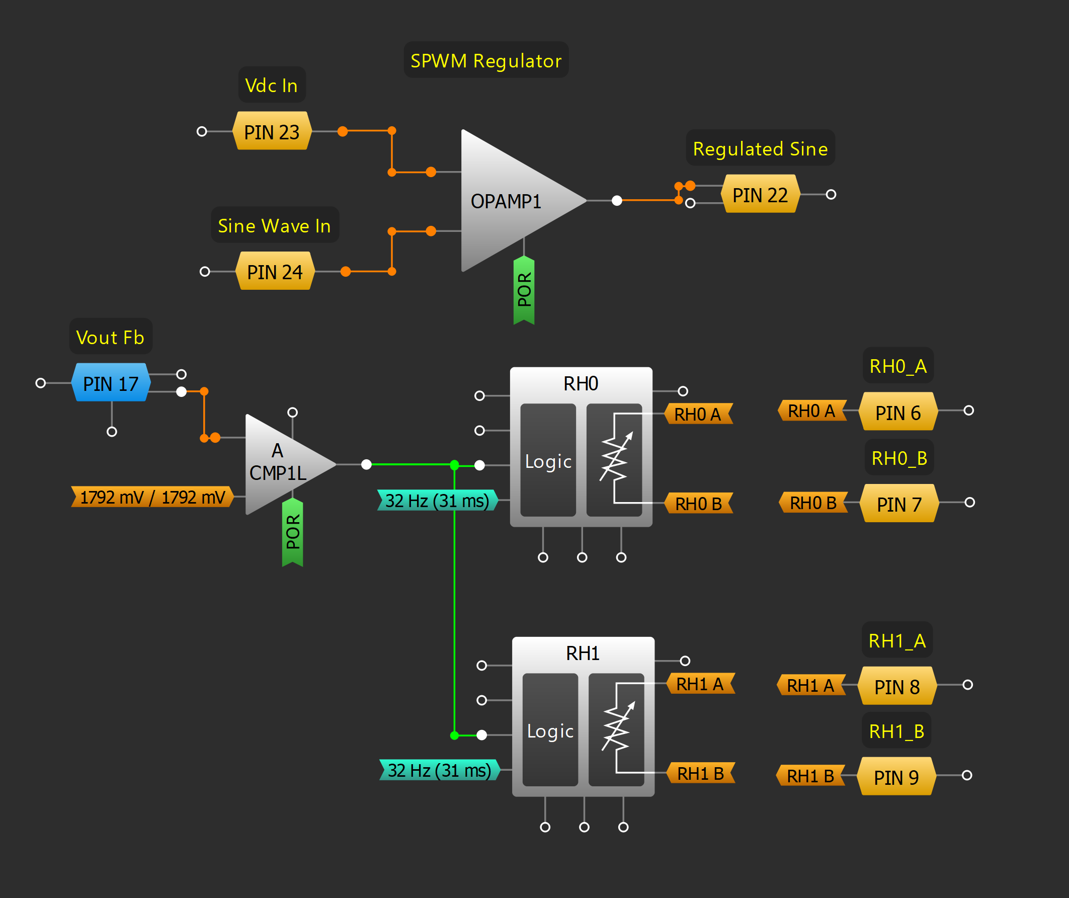
RH0 and RH1 must have the same counter value, that is, the same resistance, to allow the OPAMP1 to amplify the sine wave without distorting its offset. This amplifier has a variable gain (determined by the values of RH0 and RH1), enabling the regulator to amplify or reduce the sine waveform amplitude. This gain change is defined by the output voltage feedback.
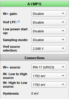
The output voltage feedback is compared to a reference fixed voltage with the analog comparator ACMP1L. If the output is higher than the reference voltage, the OPAMP1 gain goes low and if it is lower, the gain goes high.
This control is made every 31 ms, with a clock signal obtained from OSC0.
The block diagram of the voltage regulator is shown in Figure 14.
Both RH0 and RH1 are configured as rheostats, with an initial rheostat counter value set to obtain a unitary gain. Their configurations are shown in Figures 15 and 16.
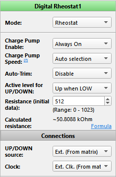
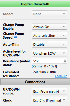
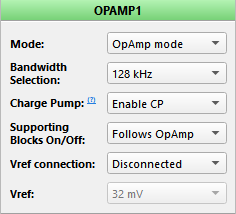
The OPAMP1 and ACMP1L configurations can be seen in Figures 17 and 18, respectively.
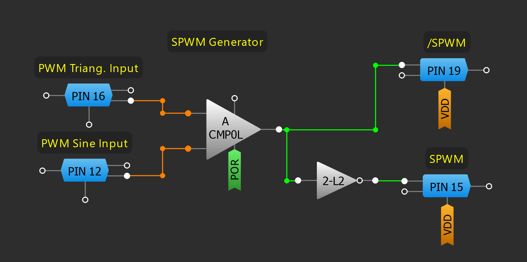
Finally, the SPWM modulator is implemented with ACMP0L and the 2-bit LUT2 is configured as an inverter. It is shown in Figure 19. In Pin 19 and Pin 15, the SPWM output and its inverted version are obtained, ready to control the H-bridge output.
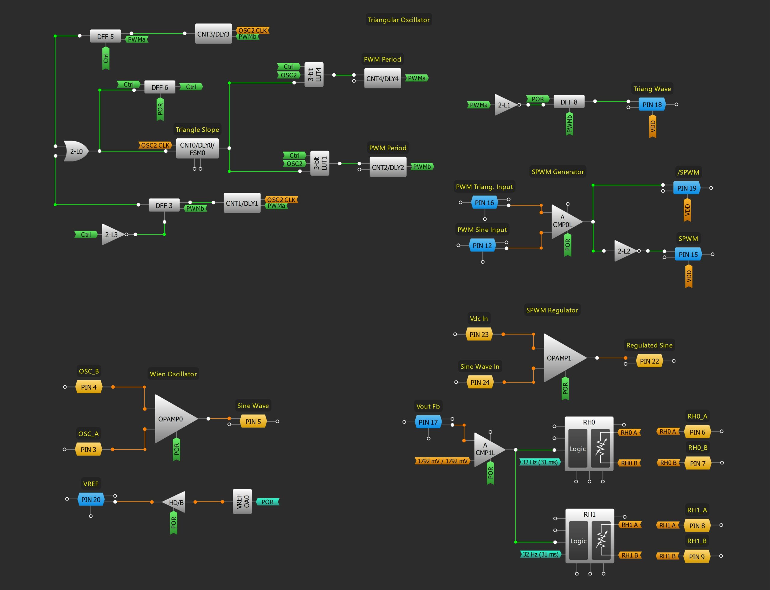
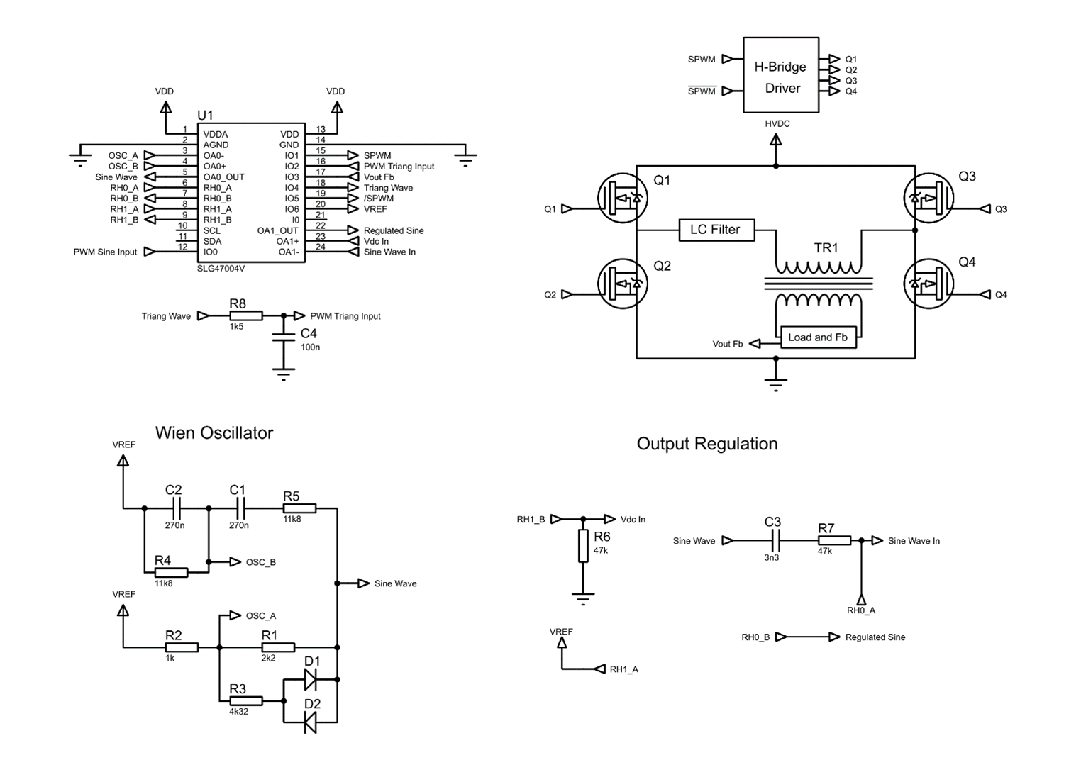
The entire block diagram of the sine wave-based inverter and the schematic circuit are shown in Figure 20 and Figure 21.
Test and Conclusion
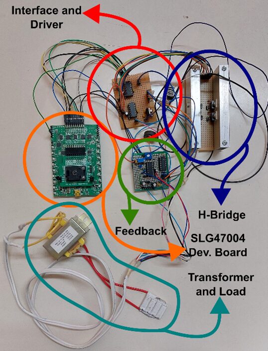
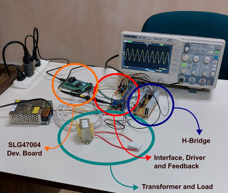
To test the implementation, the entire system was assembled. In Figure 22, different parts of the design that are assembled and interconnected are shown.
This implementation was entirely connected and analyzed with an oscilloscope.
The hardware and measurement tools can be seen in Figure 23.
To verify the results, the voltage’s waveform at the load (scaled by a feedback network) and the output signal on Pin 19 of the SLG47004 were measured.
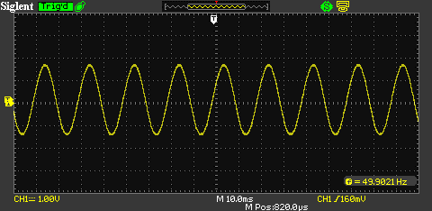
In Figure 24, the feedback of the output voltage (before the rectifier) is shown. It can be seen how the output voltage has a sinusoidal shape as was expected.
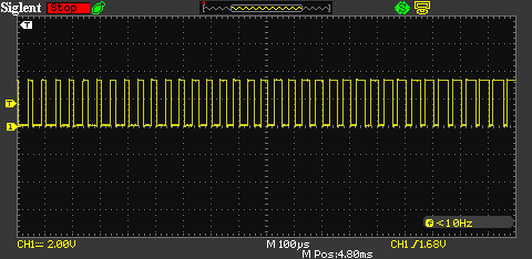
In Figure 25, the SPWM output signal at Pin 19 of the SLG47004 is shown. It can be noted the sinusoidal variation of the duty cycle at the PWM output.
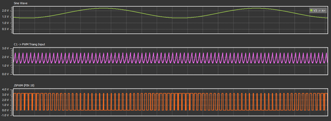
In the same way, different parts of this design were simulated using the software simulation of the Go Configure Software Hub. As this is quite a complex design, and with slow phenomena (20 ms period) if it is compared to simulation period, the first cycles of the design are shown in the simulation results.
The triangular wave oscillator and SPWM were simulated separately from the rest of the design, injecting a simulated sine wave to the sine input of the SPWM generator.
Figure 26 shows the injected sine waveform, the triangular waveform output at the simulated RC filter and the /SPWM Output (Pin 19). It can be seen how the duty cycle of the /SPWM output experiments a sinusoidal variation, as expected.
The Wien-based oscillator was also simulated. Its output, with a simulated AC coupling, is shown in Figure 27. As mentioned before, it is important to note that the first cycles are the transient cycles. However, it is useful to show the oscillation with the corresponding frequency (50 Hz).

An inverter is a key component for renewable energy applications or portable devices that require an AC voltage power supply, and sinusoidal pulse width modulation (SPWM) is one of the most used methods for implementing them.
There are several methods to implement SPWM inverters. One of the simplest and most used methods was represented in this article. It describes each step of SPWM generation and regulation, and how it can be connected to the output. The size of the entire system is smaller than many other implementations and it shows an application where the Renesas’ AnalogPAK can be used as the core of the device.


