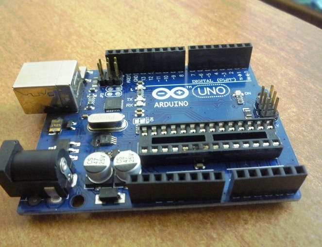
Even if you have years working with electronics, you will still find some simple hacks that you never thought about before. Personally and to save money, when I was a student with a very limited budget I knew that my Arduino UNO can work as a USB/TTL(serial) converter. I used to remove the Atmega328P from my Arduino UNO R3 board in order to use the board as a converter not as a development board.
Why we need to do some tweaking to Arduino in order to use 0 and 1 pins for direct USB <-> UART conversion? This is because of what’s called fan-out (fan-out of a logic gate output is the number of gate inputs it can drive). In Arduino UNO case, the RX & TX lines (pins 0 and 1) are connected to FT232RL/Atmega8U2 USB to TTL bridge and to the Atmega328P MCU (check the schematic). So using the same pins with an external connections without doing any changes to Arduino UNO board probably won’t work.
Patel Darshil over Hackster.io listed three ways to make Arduino works as a USB/TTL converter:
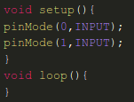
Hack #1: Set Pin 0&1 Mode to Input Mode
This is done using code:
But why this solves the problem? Well, GPIO can operate in two modes, input and output. In the input mode the equivalent impedance of the pin is too high; therefore, the Arduino/Atmega328P’s pins will have almost no electrical effect to the converter RX/TX pins.
Hack #2: Keep Atmega in Reset Mode
Just connect the RES pin with GND (the bold red wire in the image bellow)
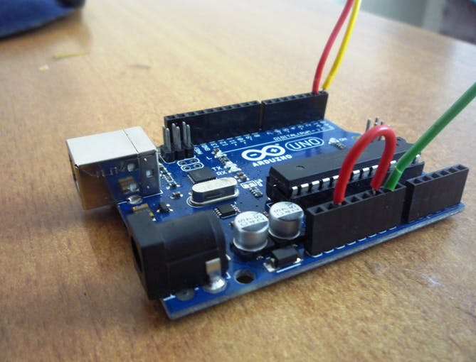
GPIOs are configured using special registers. For example, Atmega has GPIO port data direction register (DDR) to set the GPIO as an input or an output for each port. The value of this register is cleared during reset. Therefore, the MCU’s GPIOs mode will be input. This means high impedance, subsequently.
Hack #3: Remove The MCU
This is the common way used by most Arduino UNO users, but it’s not applicable when it comes to new versions of Arduino; where, the MCU is SMD and can’t be removed.


