AVR is a microcontroller family developed in 1996 by Atmel, now acquired by Microchip Technology since 2016. AVR generally refers to the 8-bit RISC architecture line of ATMEL AVR microcontrollers. They are very popular in embedded systems. They are very common in maker and hobbyist embedded applications and they are also included in Arduino boards. AVR is based on the modified Harvard architecture in which the program and data are stored in separate physical memories. They allow reading data items by special commands. In AVR architecture, Flash memory, EEPROM, and SRAM are all integrated on a single chip. This eliminates the need for external memory.
AVR Programming Methods
In-system programming uses the SPI (Serial Peripheral Interface) which is a full-duplex master-slave-based interfacing technique. The synchronization is done by the rising or falling edge of the clock applied. The disadvantages of the SPI interface are that the speed depends on the target clock and four pins are utilized in the interface. SPI is a very simple type of programming interface. Then comes JTAG which was introduced in 40 pin AVRs. In JTAG, the speed is faster and does not depend on the target clock. But it also needs four port pins for usage.
The TPI Interface was introduced in low-end microcontrollers like some selective microcontrollers in the ATtiny family. It is a 2-wire interface that uses reset as clock and another dedicated data pin. PDI interface is very similar to the TPI interface. It is fast and can cope up with a baud rate of 230,400. UPDI interface is the latest interface by Microchip technologies. It is used in almost all new AVR microcontrollers like tinyAVR, megaAVR, and AVR-Dx. This programming interface is a cross between Debug-Wire and PDI but, it only uses a single line like Debug-wire. However, it is a serial interface without a clock so, the speed is not as fast as PDI.
UPDI Programmer PCB
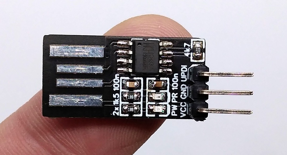
Stefan Wagner from Germany designed a simple programmer which can program new AVR microcontrollers. The USB-to-serial chip used here is CH330N. It comes in an easy SOIC-8 package and only needs few components to work. In addition, it works fine with both 3.3V and 5V. UPDI interface only needs 3 pins: VCC, GND, and UPDI. First of all, USB to serial conversion is done by the CH330N IC. Then the serial pins RX and TX are tied together with a 4k7 resistor or any suitable resistor and that node is connected to the UPDI pin of the AVR device. The schematic of the board is as follows.

The programmer works with pyupdi and Arduino IDE. pyupdi is a Python utility for programming AVR devices with the UPDI interface using a standard TTL serial port. This allows makers and designers to program AVR microcontrollers from their favorite environments and languages like Arduino IDE which uses C/C++ or Raspberry Pi environment which uses Python.
The complete project including the Gerber file can be found here: https://github.com/wagiminator/AVR-Programmer/tree/master/PyUPDI_Programmer


